Identifying Primary Warp Yarn Weakness Mechanisms in Air Jet Weaving
Warp yarn failure on air-jet looms stems from pneumatic twist disruption and drop-wire abrasion, requiring high-speed tensile screening to protect shed hours.
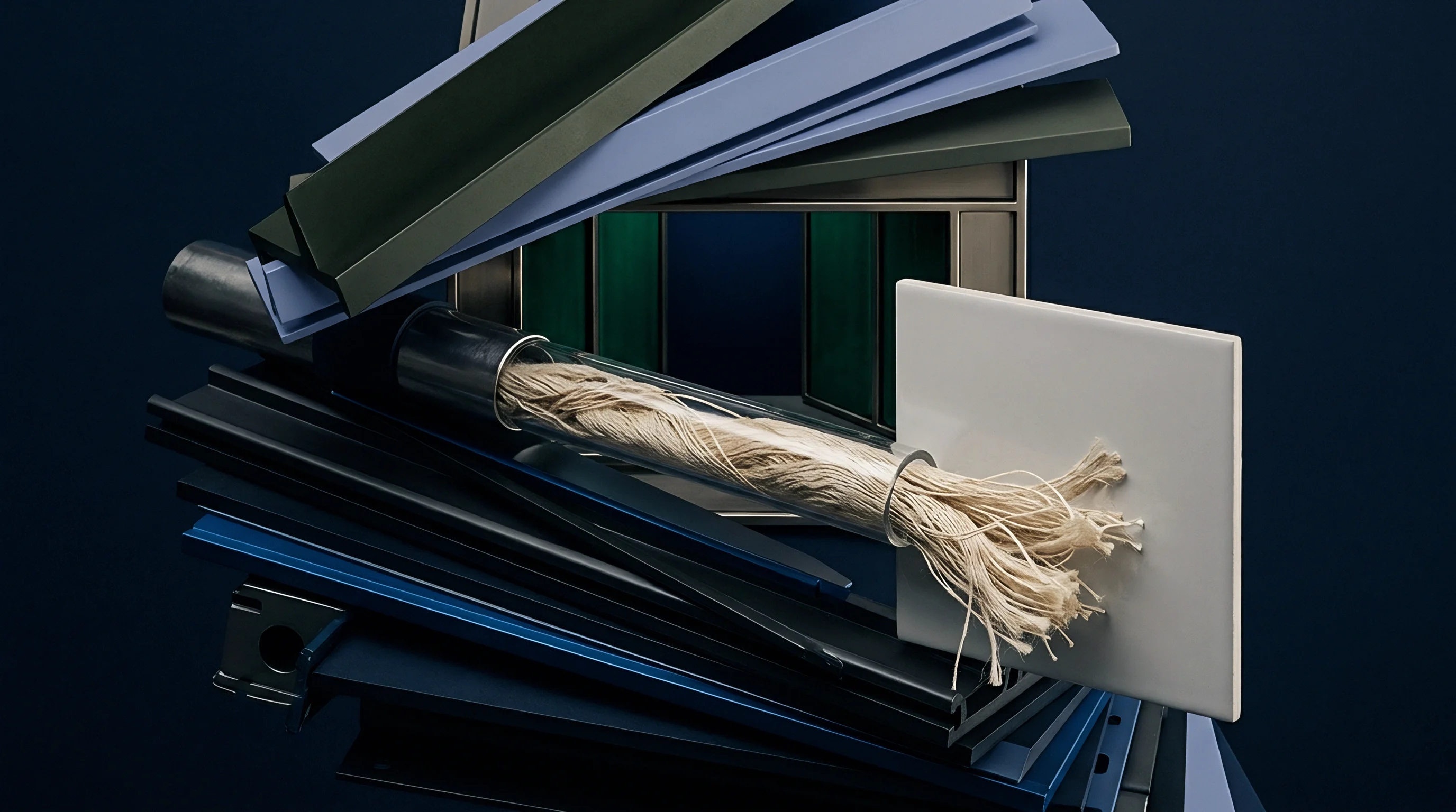

Chafe
High-velocity air-jet insertion subjects warp ends to continuous physical rubbing against metal contact points across the shedding zone. Mechanical wear concentrates heavily at drop wires, heddle eyes, and reed dents during high-speed operation. At loom speeds reaching twelve hundred picks per minute, each yarn strand passes rapidly through heddle eyes under constant mechanical tension, wearing down the outer protective size film and exposing raw surface fibers to direct abrasion.
The drop wire rests directly upon the warp yarn as an electrical contact sensor to monitor breakage. During shed opening and closing, the warp thread slides up and down through the drop wire slot. When sizing material lacks sufficient elastic toughness or surface adhesion, this friction shaves the size coating off the yarn body, generating microscopic dust that accumulates in the drop wire bank.
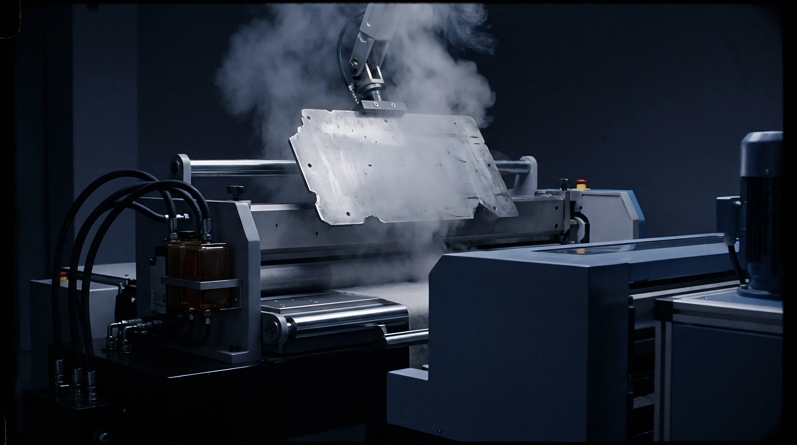
Profile Reed Abrasion and Dropper Friction Mechanics
Friction between thread strands and the profile reed channel recurs on every insertion cycle. The reed channel guides the propelled air stream and weft thread across the loom width, but warp ends brush against the metal reed dents during shed closing while air pressure remains high. If yarn hairiness exceeds quality thresholds, protruding fiber ends catch against the dent wires, causing fiber peel-back and localized core thinning.
A size film thickness below eight percent of yarn diameter fails to protect staple fibers against drop wire abrasion at loom speeds above one thousand picks per minute.
Heddle eye contact presents another critical friction point. Steel heddles hold warp threads to form the weave shed, and the rapid vertical reciprocating motion of the frames creates intense contact stress at the upper and lower apex of the eye. Yarns spun with low twist multipliers lack sufficient inter-fiber friction, allowing the steel surface to drag individual fibers out of the yarn body and form slubs that eventually block the reed dent.
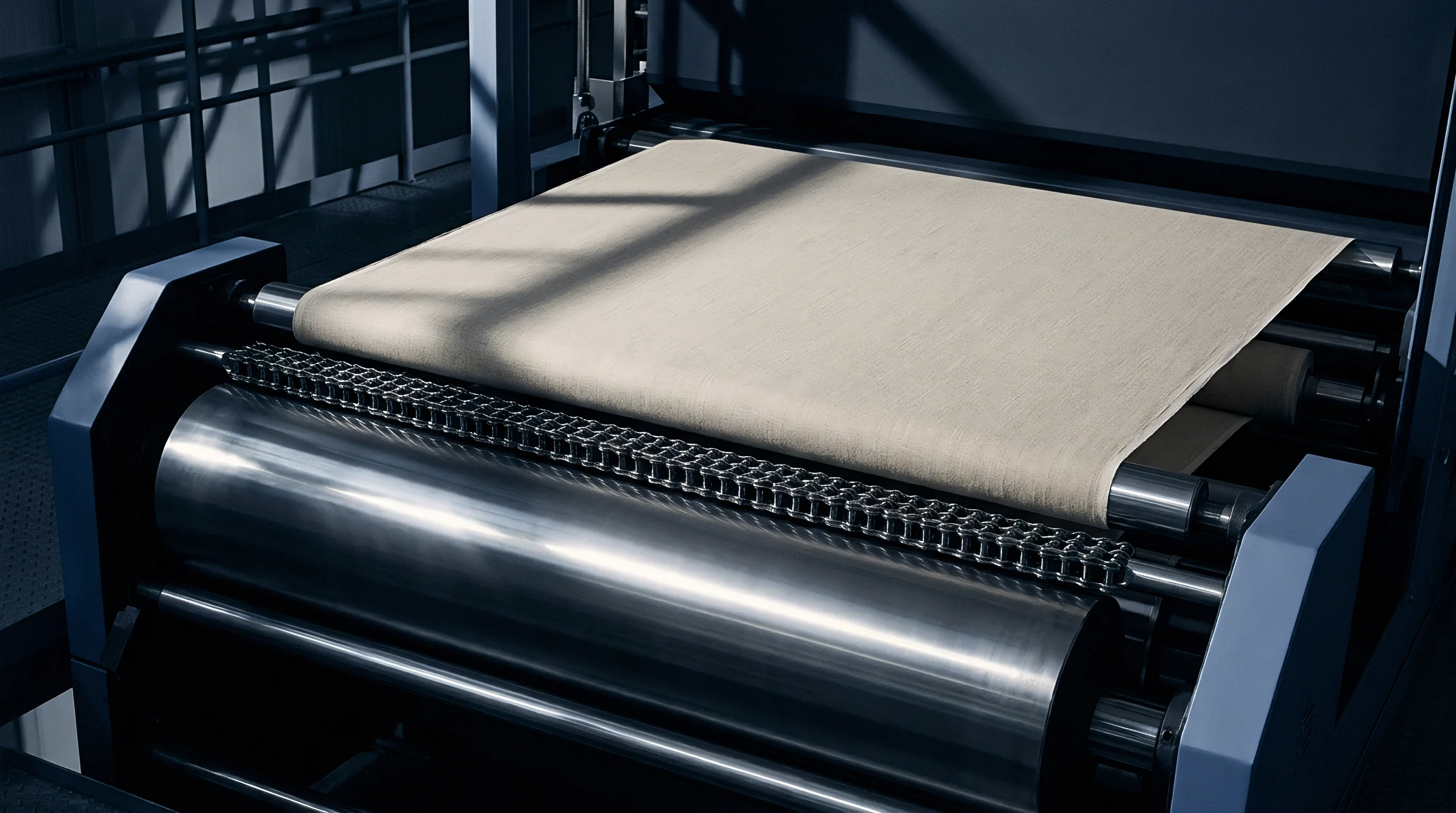
Abrasive Wear Driven by Relay Air Nozzles
Auxiliary air jets discharge pressurized streams directly into the open shed at frequencies exceeding twenty pulses per second. These targeted air blasts force adjacent warp ends sideways against neighboring threads and reed surfaces, stripping loose surface fibers from spun yarns and creating floating fly and fiber clusters inside the shed channel.
Fine-count staple yarns suffer severe abrasion when relay nozzle alignment drifts from target specifications. Misaligned nozzles drive high-pressure air into the warp sheet rather than down the center of the reed profile, forcing warp strands into dent edges. If protective sizing is inadequate, drop wire friction strips surface fibers into clinging fuzz balls that trigger warp stops and leave permanent defects across the loom beam.


Fatigue
Dynamic cyclic loading during high-speed shed opening subjects warp threads to relentless peak tension oscillations. Warp ends undergo rapid extension and relaxation, experiencing thousands of stress reversals per operating hour. Repeated mechanical stretching alters the crystalline orientation of synthetic fibers and disrupts natural hydrogen bonding within cellulosic staple fibers.
Cumulative strain hardening reduces elasticity, leaving threads brittle and increasingly susceptible to sudden tensile failure.
Peak tension spikes occur during shed opening, when heddle frames reach maximum lift height. The warp sheet stretches to form the top and bottom shed lines, raising tension far above the baseline static beam tension. On high-speed air-jet looms, shed opening happens in a fraction of a second, generating sharp tension spikes that approach the yarn’s yield point.

Shedding Tension Peaks and Cyclic Stress Profiles
Mechanical lifting of heddle frames creates rapid stress cycles reaching thirty percent of nominal yarn break strength. While the backrest roller balances tension fluctuations across the weaving cycle, high-speed mechanical inertia limits its compensating movement. Consequently, tension peaks pass directly into the warp section between the harness frames and the fell of the cloth, where repeated dynamic loading induces microscopic structural damage long before a complete yarn break occurs.
| Yarn Type and Count | Loom Speed (PPM) | Static Beam Tension (cN/end) | Peak Shedding Tension (cN/end) | Cycles to Fatigue Break |
|---|---|---|---|---|
| 100% Ring Spun Cotton Ne 40/1 | 900 | 22.5 | 48.0 | 185,000 |
| 100% Ring Spun Cotton Ne 40/1 | 1200 | 24.0 | 58.5 | 92,000 |
| 100% Wet Spun Linen Lea 40 | 850 | 35.0 | 78.0 | 34,000 |
| Polyester/Cotton 65/35 Ne 50/1 | 1100 | 18.0 | 39.0 | 410,000 |
| Filament Nylon 40d / 34f | 1250 | 12.0 | 28.5 | 850,000 |
| Data recorded on 190 cm air jet looms operating under standard mill conditions at 65% relative humidity and 22 degrees Celsius. | ||||

How Do High-Frequency Air Streams Degrade Warp Integrity?
Pressurized air strikes the yarn body at near-sonic speeds, generating localized micro-vibrations that unlay spun fiber bundles. Relay nozzles discharge compressed air at pressures between 0.25 and 0.45 MPa directly against the lower shed threads. These air pulses induce lateral vibration in the warp ends, producing rapid bending stresses that compound the longitudinal tensile strain imposed by shedding motion.
High-frequency lateral vibrations destabilize thin places within spun yarns, as thread segments with lower mass per unit length experience higher stress concentrations during air impact. Pushed by pneumatic blasts, the combination of high-speed tensile cycling and high-frequency vibration accelerates micro-crack propagation in the sizing coat, leading to catastrophic yarn snaps during beat-up.
Standard ISO 13934-1 tensile values overestimate air-jet warp performance because static pulling tests ignore high-frequency cyclic stress peaks.
Viscoelastic recovery dictates how well a warp yarn withstands continuous high-speed shedding. Elastomeric and synthetic blend yarns partially absorb cyclic shocks through elastic deformation, whereas rigid natural fibers like flax possess minimal elongation capacity. Maintaining uniform beam tension across shedding cycles prevents cumulative strain hardening and extends warp survival on high-speed weaving frames.
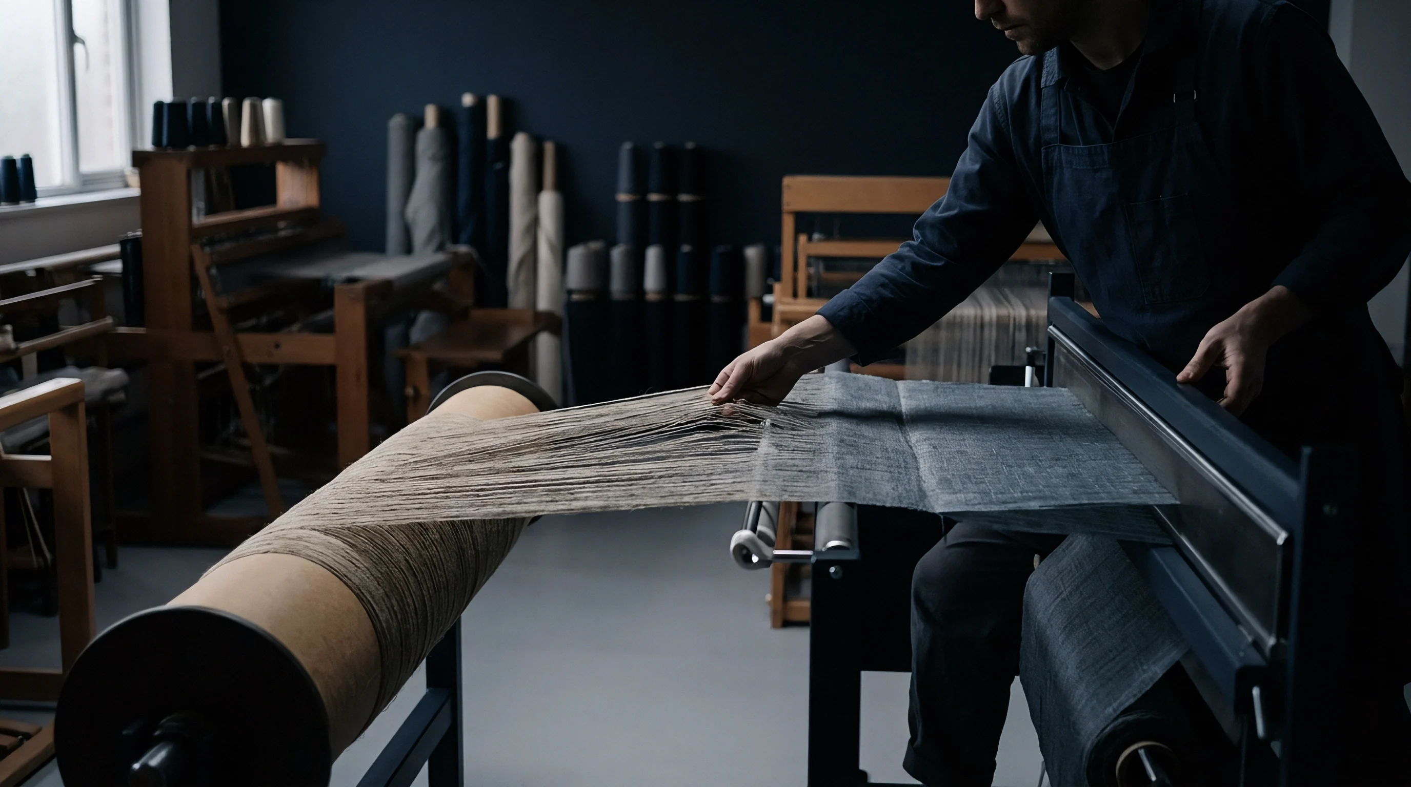
Cohesion
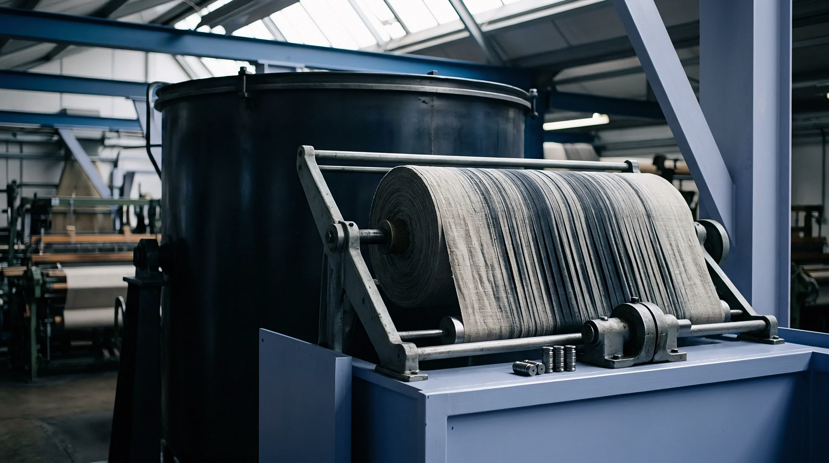
Inter-fiber bonding inside the spun bundle governs whether a yarn resists the shearing blast of main insertion nozzles. Staple fiber yarns rely on mechanical twist, fiber length, and chemical sizing adhesive to maintain structural integrity. When high-pressure air blasts hit the thread during main nozzle acceleration, expanding compressed air forces its way between individual fibers, driving them apart laterally.
Main nozzle insertion pressures exceeding 0.35 MPa generate intense aerodynamic turbulence at the reed entry point. The air stream acts as a pneumatic wedge, searching for structural irregularities in the yarn body. Weak points lacking sufficient inter-fiber cohesion open up under air pressure, causing the yarn to balloon, untwist, and split into loose individual fibers before crossing the shed.
Pneumatic Disruption of Yarn Twist and Binder Bridges
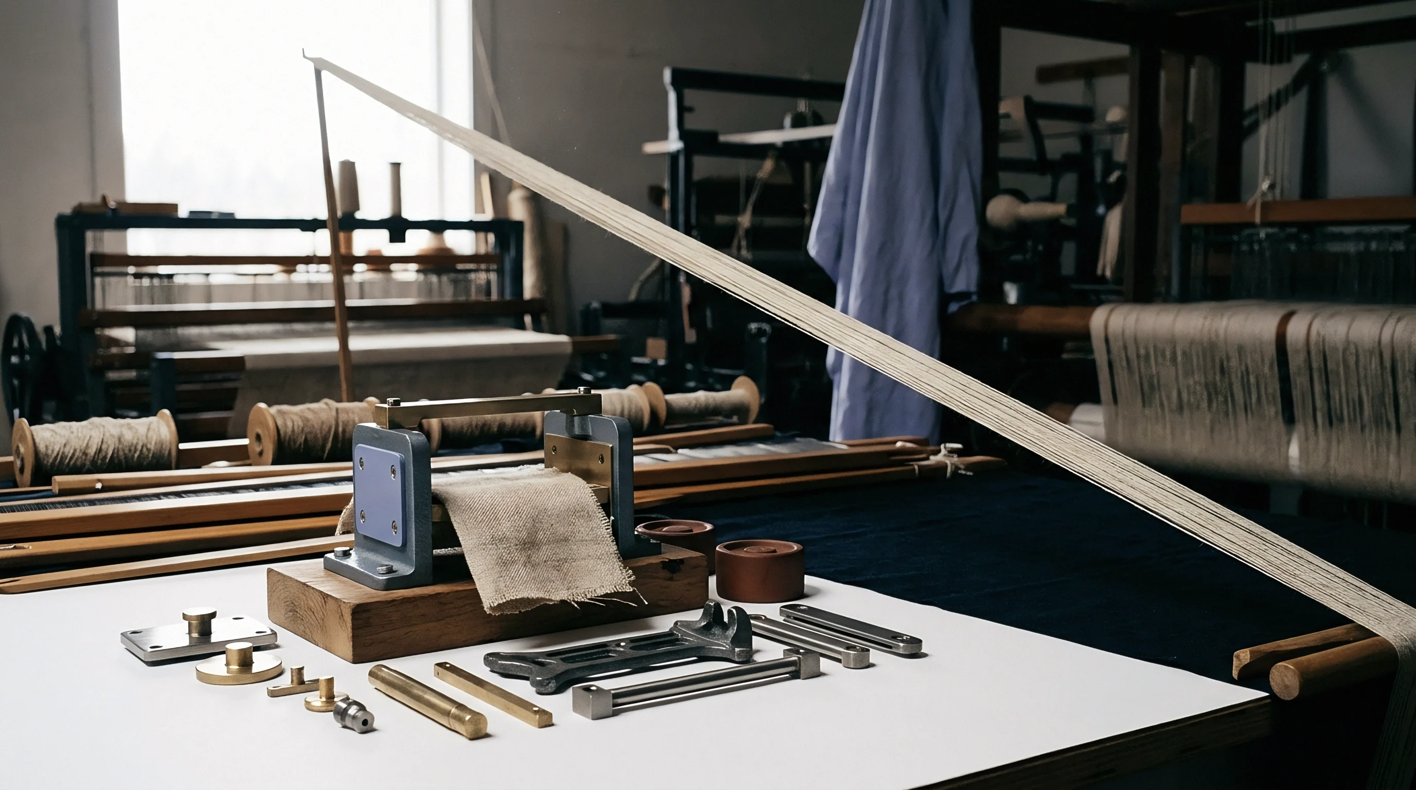
Air pressure entering the yarn channel destabilizes the twist geometry, forcing short fibers away from the core axis. While the main nozzle accelerates weft threads, trailing warp ends near the reed entry endure intense turbulent airflow. Sizing agents like polyvinyl alcohol or modified starches must form continuous film bridges between outer fibers to lock them into the spun matrix.
When sizing penetration is excessive, size material migrates entirely into the center of the yarn core, leaving surface fibers unbonded and vulnerable to air shear. Conversely, insufficient penetration yields a superficial outer shell that easily fractures under cyclic shedding loads. Balanced size encapsulation maintains surface cohesion while preserving essential yarn elasticity.

Inter-Fiber Slip and Structural Fiber Pullout
Frictional resistance between adjacent staple fibers drops rapidly when sizing binder coats fracture under pneumatic pressure. Once outer fiber ends release from the binder matrix, they align with the fast-moving air stream, pulling free from the spun core under aerodynamic drag forces. Short staple fibers slip past one another without breaking, causing yarn thinning and ultimate tensile rupture under normal shedding tension.
- Twist Displacement occurs when relay nozzle air forces the spiral arrangement of staple fibers to untwist, creating localized weak spots along the yarn axis.
- Binder Film Delamination separates the protective size coat from the outer fiber sheath, exposing unprotected raw staple ends to drop wire rubbing.
- Fiber Shearing Pullout happens when high-velocity air overcomes inter-fiber friction, dragging short fibers completely out of the yarn core structure.
- Micro-Slub Accumulation aggregates loose dragged fibers into dense clusters, blocking the reed dent gap and triggering automatic loom stops.
Low twist multipliers worsen structural fiber pullout on air-jet looms. Spinning mills often decrease yarn twist to boost softness and production throughput, but this reduction directly impairs pneumatic stability. High-speed filament separation often stems from low twist multipliers or inadequate binder penetration in the sizing bath rather than excessive air-jet pressure.
Diagnostics
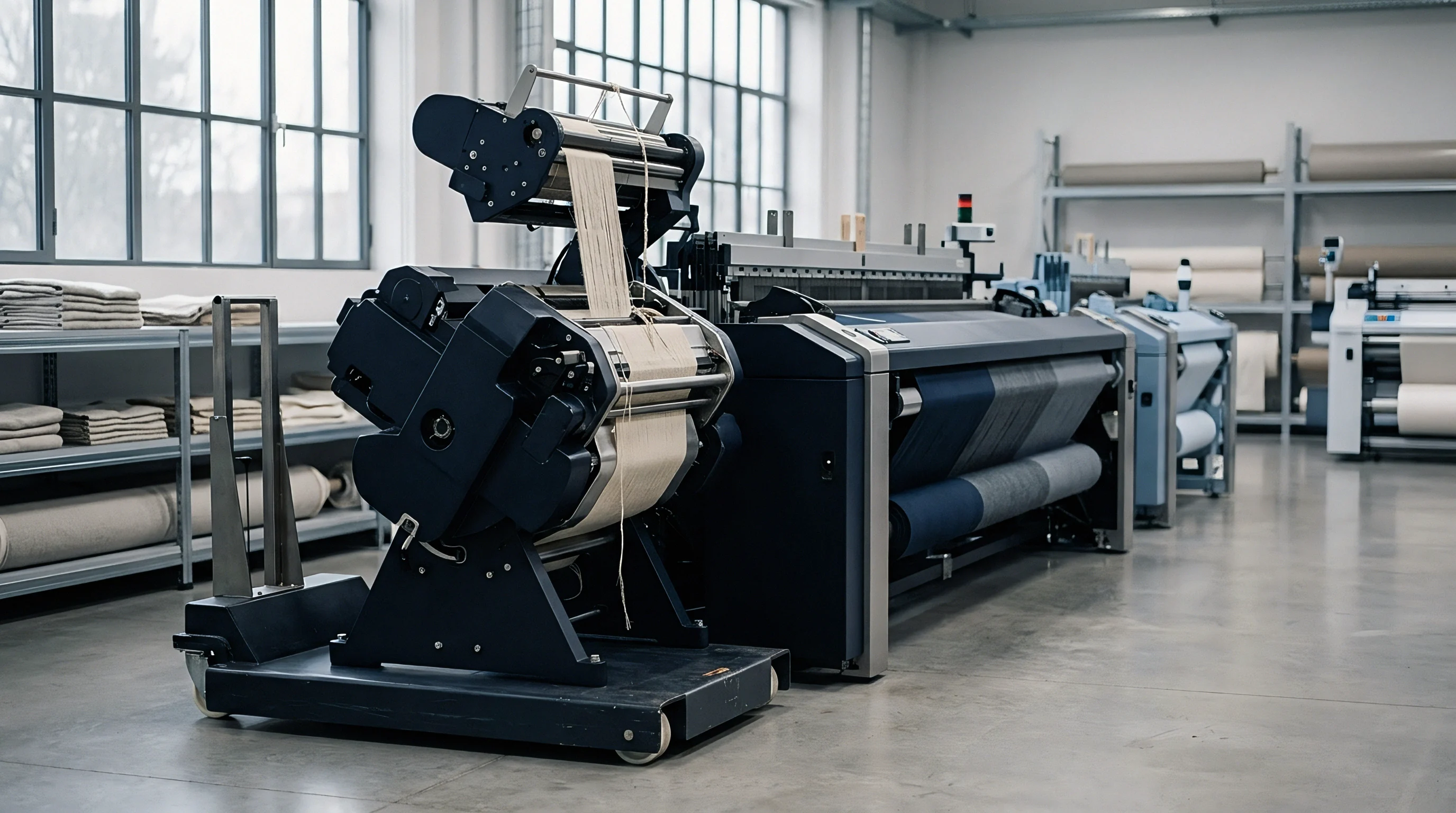
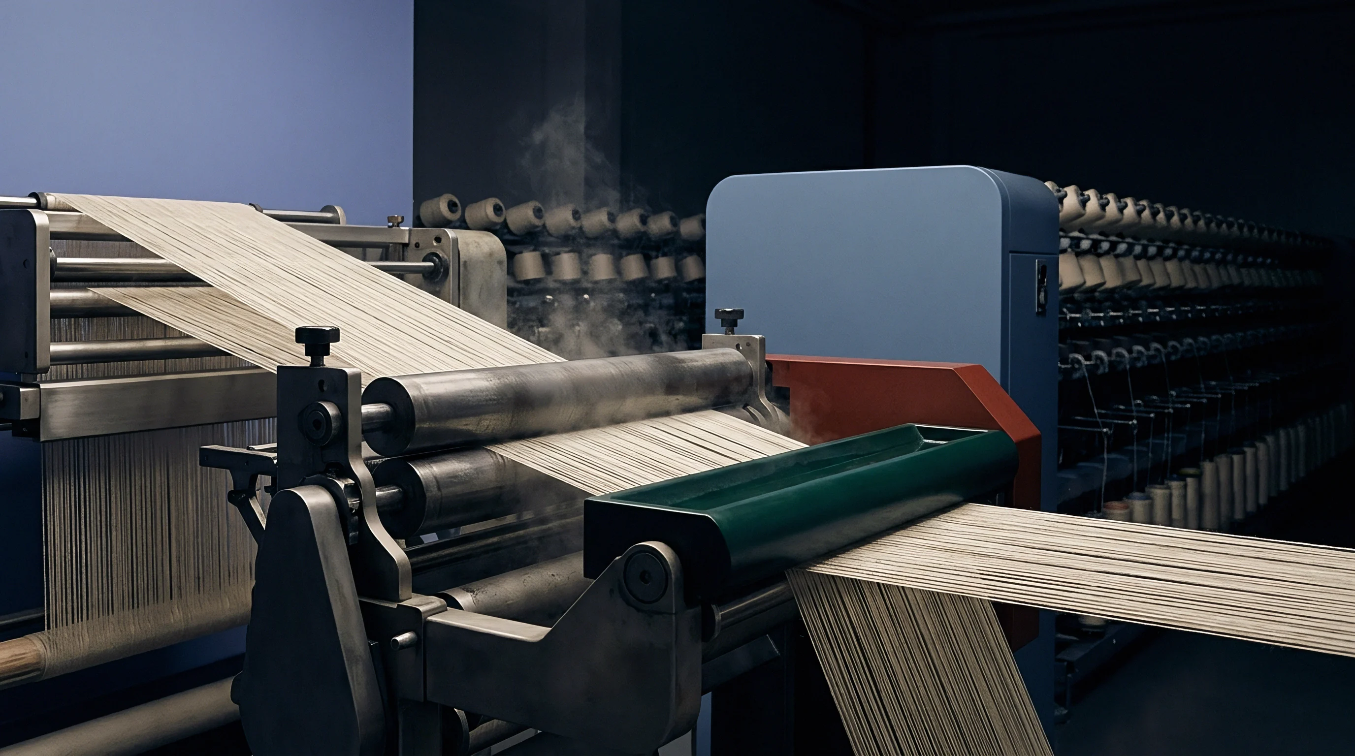
High-speed laboratory instrumentation identifies structural weak points long before warp beams enter the weave room. Standard static single-end tensile testers operate at slow speeds, failing to catch the rare low-strength outliers that cause air-jet loom stoppages. Modern quality assurance protocols require dynamic high-speed tensile testing, such as Uster Tensojet testing running at four hundred meters per minute, to evaluate hundred-thousand-meter sample runs.
Statistical distribution analysis reveals critical weak-place frequencies within yarn lots. A yarn lot possessing an acceptable average breaking force may still exhibit a wide tenacity distribution curve with severe low-strength tail defects. On an air-jet loom operating at twelve hundred picks per minute across two thousand warp ends, a weak-place rate of just three outliers per hundred thousand meters translates to multiple loom stops per hour.

Laboratory Testing Parameters for Air Jet Qualification
Tensile testing equipment operating at high speed pinpoints extreme low-tenacity outliers within large yarn packages. Testing protocols evaluate single-end breaking tenacity, elongation at break, and work-to-break energy capacity. Quality assurance routines also incorporate Classimat slub and thin-place analysis to quantify yarn imperfections that snag on drop wires or profile reed dents.
| Quality Assessment Parameter | Test Standard Method | Ring Spun Cotton Target | Combed Cotton Target | Polyester Staple Target |
|---|---|---|---|---|
| Single End Tenacity CV (%) | ISO 2062 / Uster Tensojet | < 8.5% | < 7.2% | < 6.8% |
| Elongation at Break (%) | ISO 2062 | > 6.2% | > 6.8% | > 9.5% |
| Classimat Thin Places H1/I1 (per 100km) | Uster Classimat 5 | < 15 | < 5 | < 2 |
| Zweigle Hairiness Index S3 (>3mm/m) | Zweigle G566 / ISO 16535 | < 18 | < 8 | < 12 |
| Sizing Coat Abrasion Resistance (rubs) | Custom Tenabr / Lab Friction | > 1,800 | > 2,500 | > 3,200 |

Statistical Thresholds for High Speed Loom Survival
Quality control managers establish minimum acceptable breaking force values based on statistical distribution curves rather than simple package averages. Evaluating incoming warp yarn requires systematic laboratory testing before committing packages to the sizing room creel.
- Extract ten representative bobbins from each incoming yarn lot prior to sizing preparation.
- Run 100,000 meters of continuous tensile testing on a high-speed automatic single-end tester to measure weak-place frequency.
- Evaluate Classimat short thick places and thin places per 100,000 meters of spun thread.
- Conduct Zweigle hairiness count analysis to log outer fibers extending beyond three millimeters from the core.
- Verify size coat coat-to-core ratio using chemical desizing and cross-sectional microscopic measurement.
Abrasion testing complements dynamic tensile screening. Test units simulate drop wire and heddle eye friction by rubbing sized yarn samples under controlled tension until thread failure occurs. Yarns shedding excessive size dust during abrasion tests indicate low binder coat toughness or poor adhesion to staple fibers.
- Tenacity Variance Limits dictate immediate beam rejection if the single-end breaking force coefficient of variation exceeds nine percent across package samples.
- Thin Place Cutoffs require lot rejection when Uster Classimat H1 and I1 thin fault counts exceed twelve per hundred thousand yarn meters.
- Abrasion Survival Ratings demand a minimum of two thousand rubs on custom lab friction testers before sizing film failure occurs.
- Hairiness Index Thresholds mandate that S3 values above three millimeters remain below fifteen counts per meter of thread.
ASTM D2256 breaking strength averages hide low-tenacity outliers that trigger three warp breaks per hour on high-speed air-jet looms.
Hairiness testing measures protruding fiber counts across defined length channels. Long hairs exceeding three millimeters cause fiber entanglement in the shed profile, preventing clean shed separation and triggering false warp stops. Standard purchase contracts incorporating ISO 13934-1 reference clauses allow buyers to reject entire yarn deliveries when single-end breaking tenacity falls below eleven centinewtons per tex on high-speed testing runs.


Recourse
Commercial contracts for air-jet warp beams require explicit financial adjustments when yarn failure rates inflate production costs. Poor yarn quality degrades weaving shed efficiency, driving up labor and machine overhead per produced meter of fabric. When excessive warp breaks stop high-speed air-jet looms, weaving mills incur immediate financial losses from unearned loom capacity and operator intervention delays.
Stop frequency specifications define the boundary between normal process variation and actionable yarn failure. Industry standard benchmarks expect fewer than 1.5 warp stops per hundred thousand picks on modern pneumatic looms. When break frequencies exceed three stops per hundred thousand picks, weaving efficiency drops below eighty percent, turning a profitable weaving order into a net operational loss.

Commercial Remedies for Excess Stop Frequencies
Weaving operations bill spinners for unearned overhead costs whenever warp stop frequencies exceed contract limits. Chargeback schedules assign specific dollar penalties per loom stop to compensate for lost weaver time, damaged greige cloth marks, and unearned capital depreciation costs.
| Warp Stop Rate (per 100k picks) | Loom Operating Efficiency (%) | Daily Output per Loom (meters) | Loom Overhead Cost ($/meter) | Net Financial Margin Impact |
|---|---|---|---|---|
| 1.0 (Target Benchmark) | 92.5% | 485 | $0.42 | Baseline Operational Profit |
| 2.0 (Acceptable Limit) | 87.0% | 456 | $0.48 | -$0.06 / meter margin loss |
| 3.5 (Substandard Quality) | 78.2% | 410 | $0.55 | -$0.13 / meter margin loss |
| 5.0 (Defective Warp Lot) | 68.0% | 356 | $0.67 | -$0.25 / meter loss (Full Rejection) |
Calculation of Loom Efficiency Losses and Chargebacks
Financial recovery calculations translate unearned loom hours and damaged greige meters into direct invoice deductions against yarn suppliers. When a warp beam exhibits chronic weakness, the weaving mill documents stop metrics using computerized loom monitoring systems. Machine logs record stop location, sensor type, and downtime duration, providing irrefutable proof of yarn failure.
An increase from one to four warp stops per hundred thousand picks increases finished cloth manufacturing costs by eighteen percent per loom hour.
Settlement calculations deduct the cost of wasted loom capacity from open yarn invoices. If a two-thousand-meter warp run produces twenty excess loom stops beyond the agreed contract baseline, the mill calculates the lost weaving hours, multiplies that time by the factory hourly loom rate, and applies a debit note against the yarn spinner. Suppliers facing chargebacks must either replace defective warp beams at their own expense or accept contractual debit notes reflecting the exact efficiency losses incurred on the weave room floor.