Splicing Microstructure Mechanics and Tensile Degradation under Cyclical High Frequency Rapier Shedding Stress
Water-assisted pneumatic yarn splices with optimized wrapper density reduce high-frequency shedding stress failures and protect loom efficiency on rapier sheds.

Joint
Pneumatic yarn joining replaces mechanical knots by unwinding cut yarn ends, mingling the loose staple fibers, and wrapping them under a swirling blast of compressed air. Joint integrity depends on tangled, chaotic fiber orientation rather than the continuous twist of the parent strand. On automatic winders processing single spun linen or high-tenacity cotton blends, compressed air blasts at 4.5 to 6.0 bar blow out the core twist along both overlapping ends.
The resulting turbulence forces individual bast fibers to interlock across a consolidation zone 18 to 28 millimeters long. This zone has a noticeably different structure than the rest of the yarn: while the parent strand maintains a uniform helical twist and consistent radial packing density, the pneumatic splice shows an expanded diameter, irregular fiber packing, and an untwisted central core bound by exterior wrapper filaments.
Cross-sections of a pneumatic splice reveal three distinct mechanical zones along the overlap. In the middle lies the core interpenetration zone, where parallel fiber bundles from both ends mix together. At either side are the tail transition points, where the cut yarn ends emerge and lie flat against the parent strand.
Around the outside, wrapper fibers stripped during the air blast wind around the bundle at steep helix angles above 45 degrees. Parent yarn derives its tensile strength from helical twist that converts axial load into radial clamping force. A pneumatic splice, by contrast, relies entirely on the grip of those outer wrapper fibers.
If splicing air pressure or blast timing drops below target values, wrapper density falls, leaving a loose core that pulls apart under light axial tension.
Microstructural Architecture of Air Spliced Yarns
Scanning electron micrographs show how staple fiber ends distribute across the consolidation zone. Continuous parent yarn achieves its axial strength through balanced helical packing, where twist presses outer fibers firmly against the core. Splicing disrupts that arrangement.
The nozzle injects turbulent air that untwists the incoming tips, strips loose fibrils from the surface, and drives them around the overlapping core strands to create an untwisted core encircled by transverse belts. Core fiber alignment falls from an angle of 15 degrees down to nearly zero degrees along the yarn axis, while the transverse wrappers cross at angles between 35 and 60 degrees. Tensile performance depends on the proportion of wrapper fiber volume relative to total core mass; without sufficient wrapping density, axial filaments pull out well before reaching parent strand tenacity.
Volumetric mass varies considerably across the spliced zone. A typical pneumatic join shows a linear mass increase of 20 to 50 percent over nominal yarn density along a 20 to 25 millimeter span. This localized bulge stiffens the yarn and alters surface friction, creating a physical protrusion that catches against drop wires, heddles, and reed dents during shed formation.
Linen yarns ~ which combine high flexural rigidity with low ultimate elongation ~ concentrate strain right at the boundary where the soft spliced bundle meets the dense, fully twisted parent strand. Because the tensile modulus shifts abruptly across this interface, cyclic shedding stress triggers micro-slippage at the boundary long before the core reaches ultimate tensile failure.
Chamber geometry governs how fibers move during the air blast. Prism choice determines whether air swirls clockwise, counter-clockwise, or in opposed dual-vortex streams. Dual-vortex chambers split the compressed air into two counter-rotating flows that wrap both tails simultaneously, producing symmetrical wrap angles on both ends of the consolidation zone.
Chamber width must closely match the yarn count. A chamber that is too wide permits yarn ends to flutter rather than interlock tightly, leaving a soft splice prone to slippage. An undersized chamber pinches the ends, blocking air penetration and producing a short, stiff lump with distorted surface fibers.
Sizing the chamber to the yarn’s linear density distributes wrappers evenly, preserving tensile strength without creating bulges that jam in the reed.
Fiber Interlocking and Tail Dispersal Dynamics
Tail preparation governs how cleanly cut fiber ends blend into the core during consolidation. Automatic winders use mechanical untwisting tubes and suction to strip twist from tails before they enter the splicing chamber. For wet-spun linen yarns between 20 Nm and 50 Nm, tail length requires tight regulation.
Excessively long cuts leave loose ends trailing off the surface ~ known as tail whip ~ which snag adjacent warp ends in the harness and cause loom stops. Trimming tails too short leaves insufficient overlap length inside the chamber, reducing frictional contact between fibers and allowing the core to pull apart under low dynamic loads.
Interlock efficiency across bast and synthetic strands depends heavily on fiber surface friction. Smooth, long-staple fibers like combed cotton or synthetic filaments slip past each other unless secured by dense wrapper turns. Linen fibers carry natural pectin residues and have irregular polygonal cross-sections, giving them a rougher surface that improves frictional grip within the untwisted core.
However, linen exhibits low elongation at break, typically 1.5 to 2.5 percent. Under dynamic tensile loads, bast bundles cannot stretch enough to distribute peak forces evenly across the joint microstructure. Stress concentrates on the outer wrapper fibers; once these hit their tensile limit and snap, radial clamping vanishes and the core ends pull free without further fiber breakage.
Splicing blended yarns introduces uneven fiber mechanics within the interpenetration zone. In cotton-linen or polyester-linen blends, fibers with higher elastic recovery pull back toward the core while stiffer linen fibers remain on the outside. This separation affects how the join behaves under load.
Cotton wrapper fibers stretch during shed opening, maintaining compression on the core. When low-elongation linen fibers dominate the wrapping layer instead, cyclic tensile spikes cause rapid fatigue and surface breakage. Splicing settings for blends must balance air pressure and duration to keep higher-elongation fibers in the outer wrap, shielding stiffer core fibers from direct abrasion against loom parts.
- Tail Whip Protrusion occurs when tail ends extend beyond the outer wrapper layer, creating loose fibrils that catch adjacent warp strands during shed opening and cause loom stoppages.
- Core Slip Disassembly manifests when low air blast pressure yields insufficient wrapper fiber turns, allowing central core fibers to pull past one another without structural filament rupture.
- Void Pocket Formation arises from uneven tail preparation where air turbulence traps pockets of low fiber density inside the core, creating weak points susceptible to low-load failure.
- Over-Twist Compaction stems from excessive blast duration or pressure, compressing wrapper fibers into a stiff mass that resists bending and breaks under cyclic flexing at drop wire entries.
Assessing splice quality involves checking structural metrics against parent yarn benchmarks. Breaking tenacity efficiency compares the tensile strength of the joined yarn to that of the parent strand. The diameter ratio tracks cross-sectional swelling relative to nominal yarn width, while the slip threshold marks the axial load at which core fibers begin to slide before final rupture.
The following data details operational parameters across different joining methods applied to wet-spun linen and long-staple cotton warps.
| Joining Technology | Tested Linear Density | Breaking Tenacity Efficiency (%) | Diameter Increase Ratio | Flexural Rigidity Index | Structural Slip Threshold (cN/tex) |
|---|---|---|---|---|---|
| Dual-Vortex Pneumatic Splice | 36 Nm Linen | 84.5 | 1.28 | 1.35 | 11.2 |
| Single-Vortex Pneumatic Splice | 36 Nm Linen | 76.2 | 1.42 | 1.58 | 8.7 |
| Wet Air Splice (Water Injection) | 36 Nm Linen | 89.1 | 1.21 | 1.24 | 13.4 |
| Mechanical Weaver Knot | 36 Nm Linen | 62.0 | 2.85 | 4.12 | 4.2 |
| Pneumatic Splice (Standard) | 50 Nm Cotton/Linen | 88.3 | 1.18 | 1.20 | 14.1 |
| Data gathered at 20 degrees Celsius and 65 percent relative humidity. Breaking tenacity efficiency represents single-end tensile test averages over 100 sample breaks per configuration according to ISO 2062 specifications. | |||||
Water injection during pneumatic splicing significantly improves packing density in linen yarns. Introducing a mist of water droplets into the chamber softens natural pectins on the flax surface, making the fibers more pliable. These compliant fibers wrap tightly around the core under air turbulence, expanding contact area.
As the splice dries under beam tension, hydrogen bonding between adjacent cellulose chains strengthens the structure. Water-assisted splices show higher tenacity retention, less diameter expansion, and lower flexural stiffness than dry splices, allowing them to pass through drop wires, heddles, and reeds without generating excessive friction or localized strain.
Dry splices in coarse linen yarns frequently turn out loose because the fibers resist sharp bending. Stiff flax filaments fight steep wrap angles and spring back once the air blast cuts off, loosening the outer turns and weakening radial grip on the core. Raising air pressure to 6.5 bar helps overcome fiber stiffness, but excess pressure damages surface fibrils and weakens the parent yarn near the splice boundaries.
Balancing blast pressure, chamber profile, and moisture injection produces adequate wrapper density without degrading constituent fibers.
Calibrating splice parameters to yarn structure ensures acceptable tensile efficiency downstream. Settings on the winding frame need adjusting whenever raw material lots or yarn counts change. Routine inspection under optical magnification verifies wrapper distribution across the consolidation zone, keeping weak joins out of warp preparation where they might disrupt warping, sizing, or high-speed weaving.
Running splicer air pressure half a bar below chamber optimum produces soft joins that pull apart during warp beam winding rather than under loom tension.

Strain
High-speed rapier looms subject warp yarns to severe cyclic tension during shedding and beat-up. At insertion rates between 600 and 800 picks per minute, rapid harness frame cycling splits warp ends into upper and lower sheets hundreds of times every minute. Static tension set at the warp beam accounts for only part of the peak dynamic load seen during operation.
Dynamic tension spikes as heddle eyes reach peak lift, stretching yarns across fixed machine geometries between the backrest roller and the cloth fell. These tension spikes act directly on any pneumatic splices distributed through the warp.
Shed geometry determines peak tension on every revolution of the main drive shaft. As the shed opens for rapier passage, warp yarns deflect from a straight line into an angled triangle. Opening angle, backrest height, and harness stroke dictate the total elongation imposed on the yarn.
An opening angle of 28 degrees strains spun yarns far more than a shallow 22-degree opening. If a splice sits between the harness frames and the reed during shed opening, dynamic tension stretches the jointed zone while the reed strikes outer wrapper fibers at high frequency, accelerating splice breakdown.
Cyclical Kinematics of High Speed Rapier Shedding
Harness motion curves dictate force ramp rates on warp yarns during pick insertion. Modern looms use eccentric cams or electronic rotary dobbies programmed with specific dwell angles ~ the period during which harness frames pause at full lift for rapier passage. A 120-degree dwell stabilizes the shed opening for clean rapier entry, but it holds warp ends under peak tension for a full third of each shaft revolution.
This sustained load forces wrapper fibers to maintain heavy frictional contact against core strands while strained. Shortening the dwell to 90 degrees cuts high-tension hold time, reducing mechanical fatigue across spliced sections.
Beat-up adds an instantaneous tension surge on top of the shedding curve. As the reed drives the weft into the cloth fell, the wire teeth strike the warp ends to pack the pick, forcing the yarn to absorb a millisecond-scale tension spike. In heavy constructions like high-density linen canvas or tight twills, beat-up stresses can exceed 25 cN/tex on warp ends.
Given that standard single spun linen breaks between 18 and 24 cN/tex, a splice operating at 80 percent tenacity retention sits dangerously close to its breaking point, raising the risk of warp rupture during high-speed runs.
Asymmetrical shed setups alter load distribution between upper and lower sheets. Tensioning the lower shed more tightly prevents the weft from sagging and keeps rapier travel clear across the race board. However, this raises dynamic strain on lower-shed warp ends by 20 to 35 percent compared to upper-shed ends.
Splices running on lower-shed harness frames degrade faster as a result. Balancing frame lift and tuning backrest ease-off motions helps level out these tension peaks across all active warp threads.
Do High Insertion Frequencies Exaggerate Peak Warp Tension?
Increasing loom speed from 500 to 750 picks per minute scales dynamic warp stress non-linearly due to inertia in the harness frames and backrest systems. Higher speeds narrow the window available for yarn to relax between shed cycles. At lower speeds, viscoelastic relaxation in flax fibers dissipates internal tension before the next cycle begins.
At 750 picks per minute, cycle duration drops to 80 milliseconds, eliminating that recovery period and locking stress into a continuous high-frequency vibration. This vibration causes adjacent warp ends to rub against one another, abrading splice wrapper fibers before they even reach the heddle eyes.
Dynamic warp tension peaks on an 800 pick per minute rapier loom weaving 36 Nm linen reach 22.4 cN/tex during shed clearance, exceeding the static beam tension setting by 280 percent.
Backrest ease-off mechanisms damp cyclic tension surges during shed movement. Mechanical or electronic ease-off units rock the backrest roller forward during maximum shed lift, shortening the warp path and trimming peak tension by up to 40 percent. If ease-off timing drifts out of phase with harness movement, however, it amplifies tension spikes rather than dampening them.
These exaggerated peaks push splices past their yield point, triggering irreversible micro-slippage in the interpenetration zone.
Harmonic resonance in the warp sheet creates another source of localized stress at high loom speeds. Free yarn spans between the backrest roller and drop wires act like vibrating strings prone to resonance at particular shaft speeds. When drive frequency matches the natural frequency of the tensioned warp, standing waves develop, causing violent inter-yarn abrasion and sharp tension swings.
Splices positioned at wave antinodes experience rapid surface wear and wrapper stripping, leading to unraveled joints and warp stops.
Tension variations across the loom width also drive fatigue near the selvedges, where warp ends undergo greater angular deflection from the reed and temples than central ends do. Spliced yarns running within 10 centimeters of the selvedges face continuous lateral shearing alongside regular shedding strain. Lowering shed height near the edges through linked harness frames caps peak tension and protects splices across the full width of the warp.
Unchecked shed tension spikes unravel pneumatic splices on high-speed rapier equipment, causing frequent loom stops that drag down weaving efficiency and mark the fabric.
Fatigue
Cyclic shedding stress degrades pneumatic splices progressively rather than through sudden tensile fracture. Initial shed cycles stretch outer wrapper fibers and pull them into alignment with the yarn axis. Over thousands of cycles, microscopic slip develops between the wrappers and the central core, shifting wrapper fibers toward the ends of the splice zone and leaving the core uncompressed.
As radial pressure drops, central filaments lose frictional grip and slide past each other under normal working tension.
Abrasive contact with metal loom parts speeds up this structural breakdown. Drop wires, heddles, and reed dents rub continuously against passing warp threads. During weaving, any single point on a warp yarn passes through its heddle eye up to 200 times before reaching the cloth fell.
Bulkier pneumatic splices suffer heavier abrasive contact in drop wire slots and heddle eyes. This friction strips away outer wrapper fibers, which gather as lint balls at drop wire entries, causing false warp stops or entangling neighboring ends.

Progressive Fiber Migration under Repeated Shedding Cycles
Microstructural analysis of splices subjected to cyclic tension shows clear fiber migration patterns over extended shed runs. Fibers originally locked in the core work their way outward under repeated axial stretching and bending, raising core porosity and shrinking the contact area between overlapping ends. In bast yarns, rigid flax elementary fibers detach from their surrounding pectin matrices under continuous cycling and migrate outward as loose surface fuzz.
This migration weakens the core interlock and raises friction against loom components.
Flexural fatigue compounds tensile wear as splices pass through heddle eyes, where the yarn bends at angles up to 15 degrees under peak dynamic load. High flexural stiffness in the enlarged splice zone concentrates bending strain right at the boundary with the more flexible parent yarn. Rigid linen fibers resist this cyclic flexure and develop microscopic transverse cracks.
These micro-cracks lower individual fiber strength, triggering progressive filament breakage along the outer perimeter until remaining core fibers can no longer support peak shedding tension.
Stored strain energy causes permanent mechanical deformation over prolonged weaving cycles. Viscoelastic fibers undergo plastic elongation under cyclic load: while parent yarn stretches and recovers elastically, pneumatic splices absorb strain through permanent displacement of untwisted core fibers. The splice zone lengthens and its diameter contracts slightly, slackening wrapper tension.
This drop in internal clamping accelerates progressive core slip toward structural failure.
Frictional Abrasion and Shear Stress Concentration
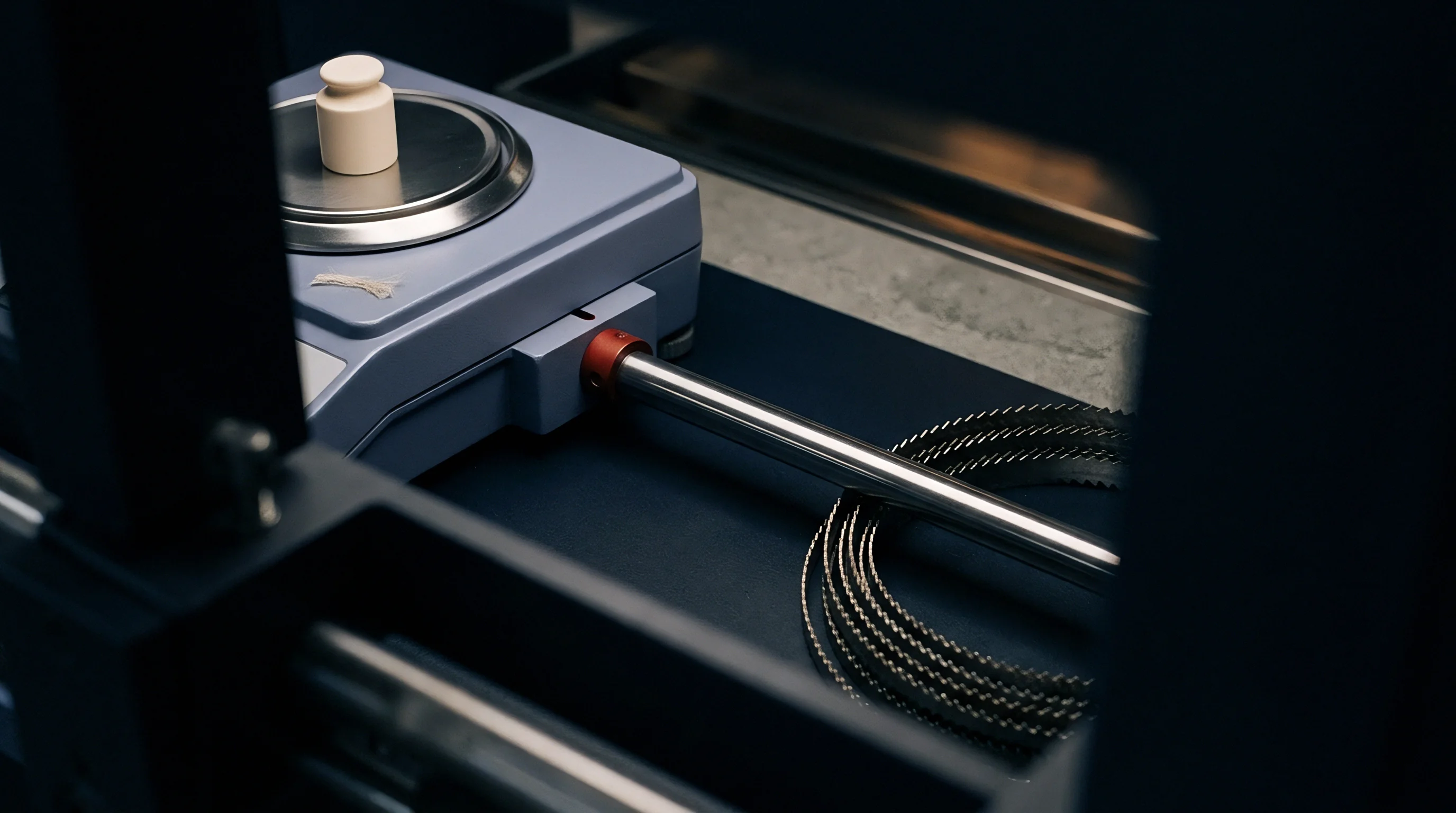
Abrasion against heddle eyes converts axial warp tension into transverse shear across outer splice filaments. Even polished or ceramic-coated heddle eyes exert localized normal forces against passing yarn bulges. As an enlarged splice forces through the eye opening, shear stress strips away transverse wrapper turns.
Stripped of lateral support, the untwisted core filaments fan out into flat ribbons that catch on reed dents during beat-up, causing immediate warp breaks.
Standard purchasing specifications for high-speed linen warp beams require pneumatic splices to maintain a minimum of 75 percent tensile strength retention after exposure to 30,000 simulated loom shedding cycles.
Electrostatic charging increases surface friction and fiber migration in synthetic and blended yarn splices during high-speed operation. Rapid contact and separation between yarns, drop wires, and reed teeth build static charges on hydrophobic fibers, repelling wrapper ends outward away from the splice axis. These flared ends abrade neighboring warp threads and create high-friction clusters.
Applying anti-static sizing agents or keeping weave room relative humidity above 65 percent grounds surface charge and keeps wrapper fibers seated against the core.
Splice failures fall into two distinct modes under cyclic fatigue. Fast structural rupture occurs within the first 1,000 shed cycles when peak shedding tension exceeds the static strength of an improperly consolidated splice. Slow fatigue failure unfolds over 10,000 to 40,000 cycles through gradual wrapper abrasion, fiber migration, and eventual core slippage.
The table below outlines this degradation process for pneumatic splices in wet-spun linen warps tested on a laboratory shed simulator.
| Accumulated Shed Cycles | Tensile Strength Retention (%) | Splice Diameter Expansion Ratio | Core Fiber Pull-Out Index | Surface Lint Accumulation (mg/splice) | Dominant Degradation Mechanism |
|---|---|---|---|---|---|
| 0 (As-Spliced) | 86.2 | 1.25 | 0.05 | 0.00 | Baseline Structural Alignment |
| 10,000 | 82.4 | 1.29 | 0.12 | 0.18 | Wrapper Fiber Stress Relaxation |
| 20,000 | 77.8 | 1.36 | 0.28 | 0.45 | Heddle Eye Friction & Fibril Stripping |
| 30,000 | 71.5 | 1.44 | 0.54 | 0.89 | Radial Fiber Migration & Core Loosening |
| 40,000 | 62.1 | 1.58 | 0.87 | 1.42 | Sequential Wrapper Rupture & Core Slip |
| 50,000 | 44.3 | 1.75 | 1.65 | 2.15 | Total Structural Disassembly / Failure |
Tracking cumulative lint generation per splice provides a reliable indirect measure of mechanical fatigue. High lint accumulation signals wrapper breakdown and warns of impending core pull-out failures on active looms. Routine cleaning of drop wire banks prevents lint clusters from binding adjacent ends together.
Higher splice mass is sometimes thought to provide extra security, but larger bulk actually increases abrasive contact against heddle wires and accelerates structural breakdown.


Analysis
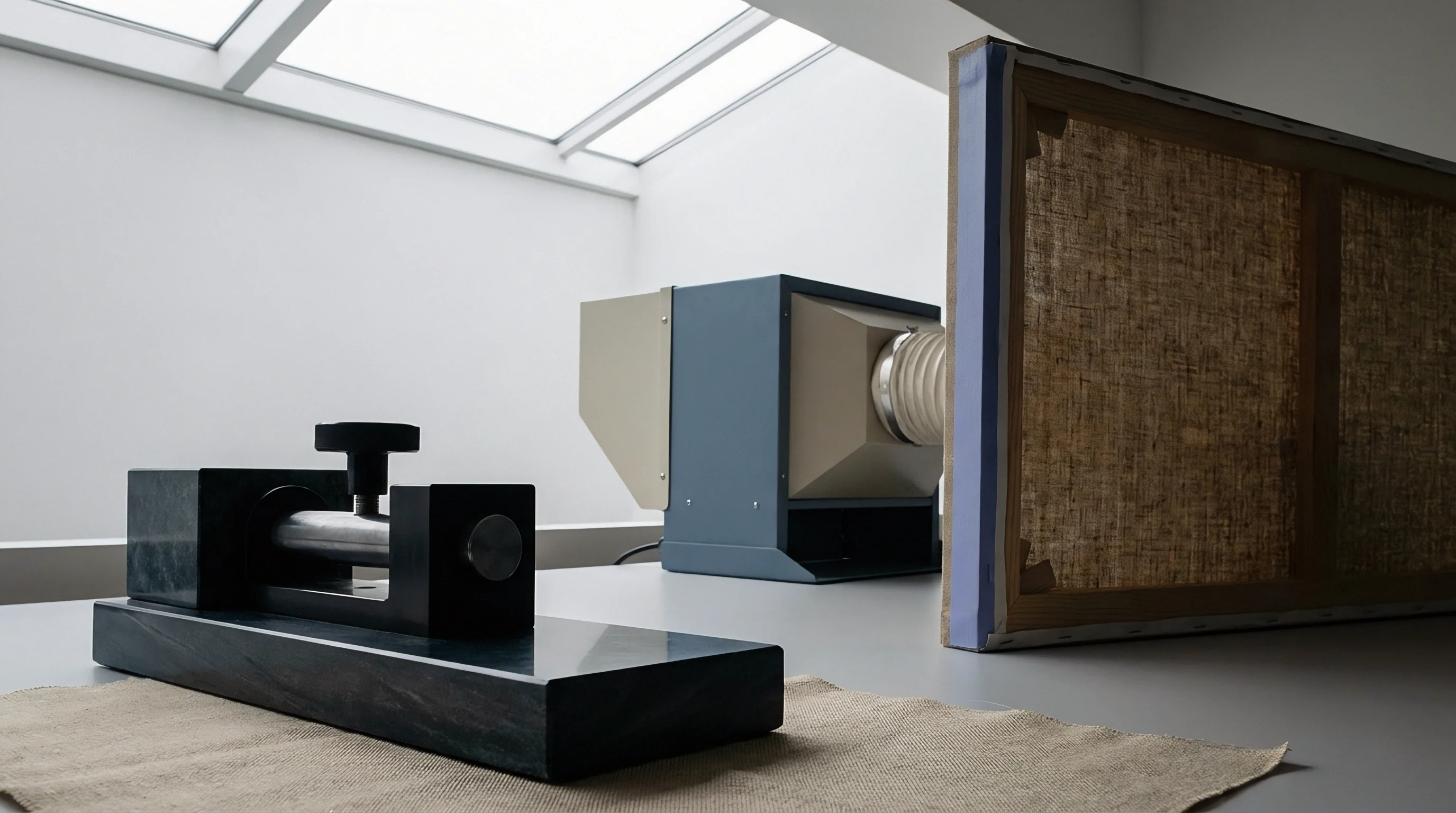
Assessing pneumatic splice performance under realistic operating conditions requires more than basic static tensile testing. Standard single-end tensile tests pull yarn joins at constant strain rates to measure ultimate load and elongation, but they miss the progressive wear caused by cyclic strain, metal abrasion, and dynamic bending inside an active loom shed. Thorough qualification relies on dynamic shed fatigue simulators that replicate loom geometry, harness stroke speeds, backrest motion, and reed abrasion under controlled atmospheric conditions.
Dynamic simulators cycle warp yarn specimens between baseline static tension and peak shed strain at production frequencies. Specimen carriages cycle splices through drop wire slots, heddle eyes, and reed dent segments during tensioning. Load transducers track dynamic tension decay across thousands of cycles to pinpoint where wrapper slippage begins, while optical cameras record wrapper uncoiling, diameter changes, and fiber migration in real time.
Laboratory Bench Protocols for Shed Stress Simulation
Standardized bench evaluations follow strict protocols to generate reproducible failure data. Because bast fiber mechanics vary with ambient humidity, sample moisture must be stabilized beforehand. Conditioning yarn specimens at 20 degrees Celsius and 65 percent relative humidity for 24 hours ensures consistent fiber compliance and friction values.
Testing bone-dry linen splices yields artificially brittle behavior and premature wrapper failure compared to conditioned samples run under standard weave room conditions.
Dynamic fatigue testing follows a structured sequence of mechanical steps.
- Mount conditioned yarn specimen carrying a central pneumatic splice into dynamic tension simulator clamping jaws set to a gauge length of 500 millimeters.
- Adjust simulator stroke length and harness linkage parameters to replicate target loom shed opening angles and static warp line tension levels.
- Position drop wire assembly, ceramic heddle wire eye, and stainless steel reed dent section along the specimen path to reproduce precise machine contact friction points.
- Initiate dynamic cycling at 11.6 Hertz, matching an operational loom insertion speed of 700 picks per minute under constant environmental control.
- Stop cycling automatically at predefined intervals of 10,000 cycles to execute static tension breaks according to ISO 13934 protocols, measuring residual breaking tenacity.
Shifts in force-elongation curves before and after cyclic testing illustrate internal structural damage. Uncycled splices exhibit clear yield points followed by steep linear load regions up to initial fiber break. Cycled splices show elongated non-linear initial curves, reflecting slack absorption within loose core filaments before load transfer occurs.
Lower initial curve slope indicates loss of internal structural compression, pointing directly to wrapper fiber displacement or fiber end slipping within the central consolidation zone.
Weibull Distribution Modeling of Splice Rupture Mechanics
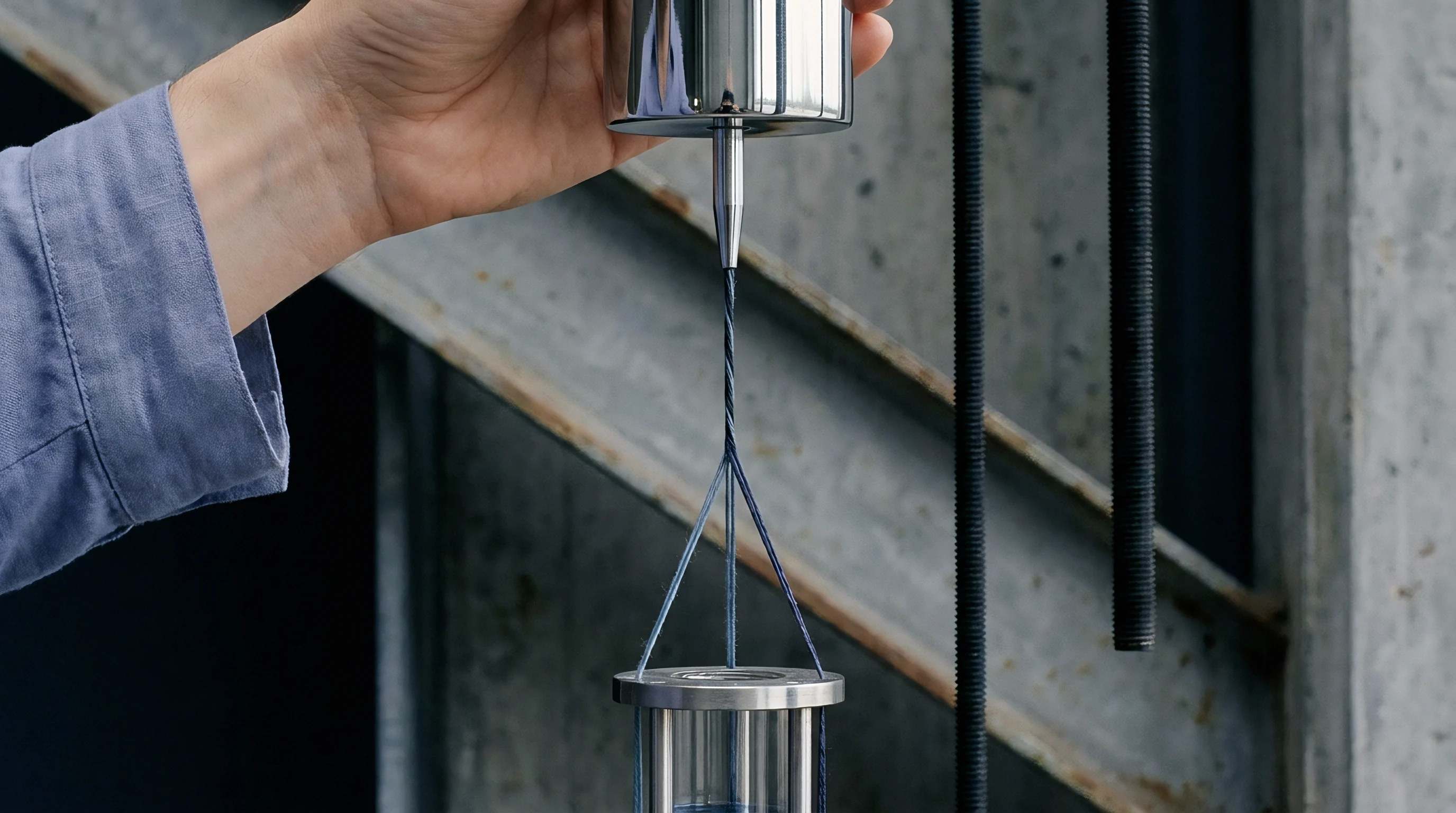
Splice failure distributions under cyclic shedding stress are modeled using two-parameter Weibull statistics. Weibull analysis yields two core values: the shape parameter, which indicates failure mode characteristics, and the characteristic life parameter, representing the cycle count where 63.2 percent of test samples fail. A shape parameter below 1.0 points to infant mortality from defective splicing parameters or damaged fiber ends.
Values between 1.5 and 2.5 indicate wear-out failures driven by cyclic fatigue, abrasion, and core pull-out. Splicing optimization aims to maximize characteristic life while tightening the shape parameter distribution to ensure consistent performance across the entire warp beam.
Splice failure populations displaying Weibull shape parameters above 2.0 indicate predictable, fatigue-dominated degradation, allowing mill managers to schedule beam changes before warp end break rates rise exponentially.
Comparative Weibull modeling between dry and water-assisted splices demonstrates distinct characteristic life differences. Water-assisted splices on 36 Nm linen yarns achieve characteristic lives exceeding 65,000 cycles on shed fatigue simulators, compared to 38,000 cycles for dry pneumatic splices. The higher shape parameter for wet splices reflects greater structural consistency, lowering early failure rates during weaving.
Winding units equipped with water-injection splicing reduce warp breaks accordingly.
X-ray micro-tomography provides three-dimensional imaging of internal fiber packing without requiring destructive cross-sectioning. These scans map void distribution, fiber orientation vectors, and tail interpenetration depth. Images taken at progressive fatigue stages show internal voids merging into continuous slip planes prior to failure.
Digital volume correlation tracks individual fiber segment displacement, proving that core fibers slip internally long before surface wrapper rupture becomes visible under light microscopy.
Defining maximum allowable splice failure rates in yarn purchase agreements establishes clear operating standards for spinning mills and weaving sheds. Supply contracts should specify minimum breaking tenacity retention and Weibull characteristic life under standard simulator bench protocols. Warp lots failing these thresholds can be rejected prior to mounting, preventing loom downtime and fabric defects.
Specifying a warp yarn batch based on static tensile strength alone leads to high loom stoppages if the splice geometry exhibits low dynamic fatigue resistance under cyclic shedding strain.

Adjustment
Careful loom adjustment minimizes the dynamic tension peaks and abrasive wear that damage pneumatic splices during shedding. Key machine adjustments include easing shed opening angles, adjusting harness timing, optimizing ease-off kinematics, and applying protective sizing films. Machine setups must balance fabric density against yarn stress limits: dense constructions require heavy beat-up force and clear shed openings, but settings must still avoid over-straining delicate warp splices during rapier insertion.
Adjusting the backrest roller shifts warp line geometry and rebalances tension between the upper and lower sheds. Raising the backrest 15 to 25 millimeters above the horizontal center line slackens upper-shed ends during harness lift while tightening the lower shed. This asymmetrical setup reduces strain on upper-shed yarns as they flex through the heddles.
Conversely, lowering backrest height reduces the shed opening angle at the drop wires, cutting lateral friction against the wire slots and extending splice life during high-speed runs.
Optimizing Loom Dwell and Rapier Crossing Timing
Shed timing determines when the shed opens relative to the main shaft angle. Advanced shed timing opens the shed early, reaching full clearance before the rapier head enters the warp sheet. While this prevents the rapier tip from striking warp ends, it holds the yarns under peak tension for a longer arc of shaft rotation, increasing fatigue on pneumatic splices.
Retarding shed timing shifts the opening closer to rapier entry, shortening dwell time under peak tension and easing splice wear, though it requires precise rapier alignment to avoid mechanical collisions.
Dobby cam profiles govern harness acceleration and velocity. Standard symmetrical cams accelerate frames rapidly, producing sharp tension spikes at the start of shed lift. Modified sinusoidal or parabolic cams accelerate harness frames more gradually, spreading load evenly across the movement cycle.
This smooth profile eliminates shock loads on pneumatic splices, reducing peak dynamic tension by up to 18 percent compared to high-acceleration eccentric cams at identical pick speeds.
Lowering shed height reduces total harness travel, cutting axial strain on the warp during shed opening. Dropping shed height from 65 millimeters to 55 millimeters lowers peak warp tension by 22 percent on high-speed rapier looms. However, smaller shed openings leave less clearance between upper and lower sheets, raising the risk of rapier interference if yarns sag.
Using reduced shed heights requires uniform warp tension, precise reed alignment, and effective sizing to prevent ends from clinging together.
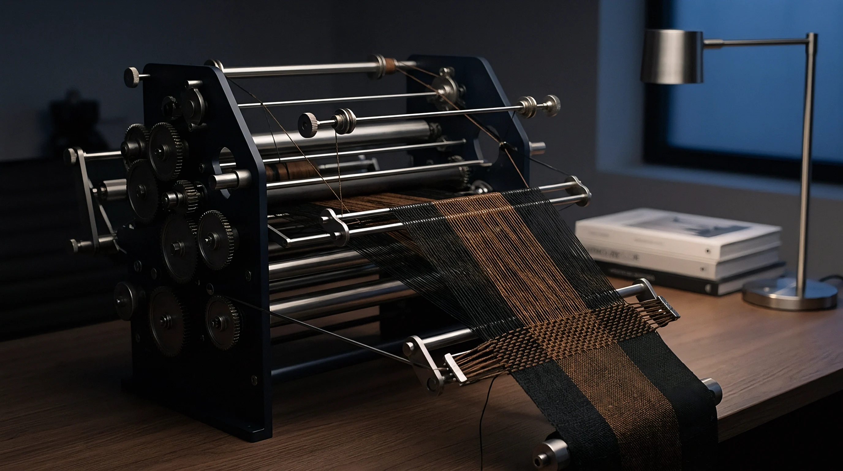
Warp Tension Compensation and Backrest Configuration
Electronic ease-off systems use servomotors synchronized with the loom drive shaft to move the backrest roller in step with harness motion. These units feed extra warp length into the shed zone exactly as harness frames hit peak lift, keeping warp tension stable throughout shaft rotation. Active tension smoothing eliminates static-to-dynamic tension spikes and preserves splice integrity, provided the ease-off stroke amplitude and phase angle are properly calibrated to yarn elasticity.
Sizing formulations and add-on rates provide physical surface protection as splices pass through the shedding zone. Polyvinyl alcohol and modified starches form flexible films over the yarn, laying down surface fuzz and binding outer wrappers to the splice core. High-performance sizing for bast fibers incorporates film-forming polymers that enhance abrasion resistance without making the yarn overly stiff.
Add-on rates between 10 and 14 percent by weight coat the splice profile, allowing it to glide through drop wires and heddles with minimal friction.
Adjusting drop wire bank distance relative to the backrest roller modifies the yarn entry angle through the drop wire slots. Moving the banks closer to the backrest reduces angular deflection during shed opening, lowering lateral shear forces against surface wrapper fibers. The table below summarizes loom adjustments designed to reduce splice failure rates on fine, sensitive spun warps.
| Operational Parameter | Standard Setting Baseline | Optimized Splice-Protection Setting | Dynamic Tension Reduction (%) | Splice Break Frequency Impact |
|---|---|---|---|---|
| Shed Opening Angle | 28 Degrees | 23 Degrees | 18.5 | 35% Reduction |
| Harness Dwell Angle | 120 Degrees | 90 Degrees | 12.0 | 22% Reduction |
| Backrest Roller Height | 0 mm (Level Line) | +15 mm (Asymmetrical) | 14.2 | 28% Reduction |
| Shed Crossing Timing | 300 Degrees (Early) | 325 Degrees (Late) | 8.7 | 15% Reduction |
| Size Add-On Percentage | 8.5% Starch | 12.5% PVA/Starch Blend | N/A (Surface Film) | 42% Reduction |
Applying systematic shed adjustments extends splice working life during high-speed production. Weave room technicians should verify warp tension across all harness frames with digital tensiometers during setup, and regularly calibrate electronic ease-off systems to prevent mechanical drift from introducing damaging tension spikes over long shifts.
Can asymmetric shed settings eliminate splice breakage entirely when weaving coarse linen yarns at full loom speed?
Yield
Warp breaks caused by failed pneumatic splices directly impair shed efficiency, loom utilization, and finished fabric costs. When an end snaps at a degraded splice, the corresponding drop wire falls, closing an electrical circuit and triggering an immediate stop. High-speed rapier looms running at 750 picks per minute lose productive capacity on every stoppage.
Downtime includes drop wire detection, weaver transit, finding the broken end, drawing it manually through drop wires, heddles, and reed dents, and restarting the loom. Total stoppage time averages 2.0 to 4.5 minutes per break, depending on weaver set allocations and shed automation levels.
Calculating the financial loss from splice failures involves tracking lost loom hours, weaver labor, greige mending, and price discounts on second-quality goods. A shed operating 100 rapier looms on dense linen fabrics faces substantial profit losses if splice breaks rise from 0.5 to 2.5 stops per loom hour. That increase lowers shed efficiency from a target 88 percent down to 72 percent, reducing daily yardage while fixed capital depreciation, power draw, and plant overhead stay fixed.
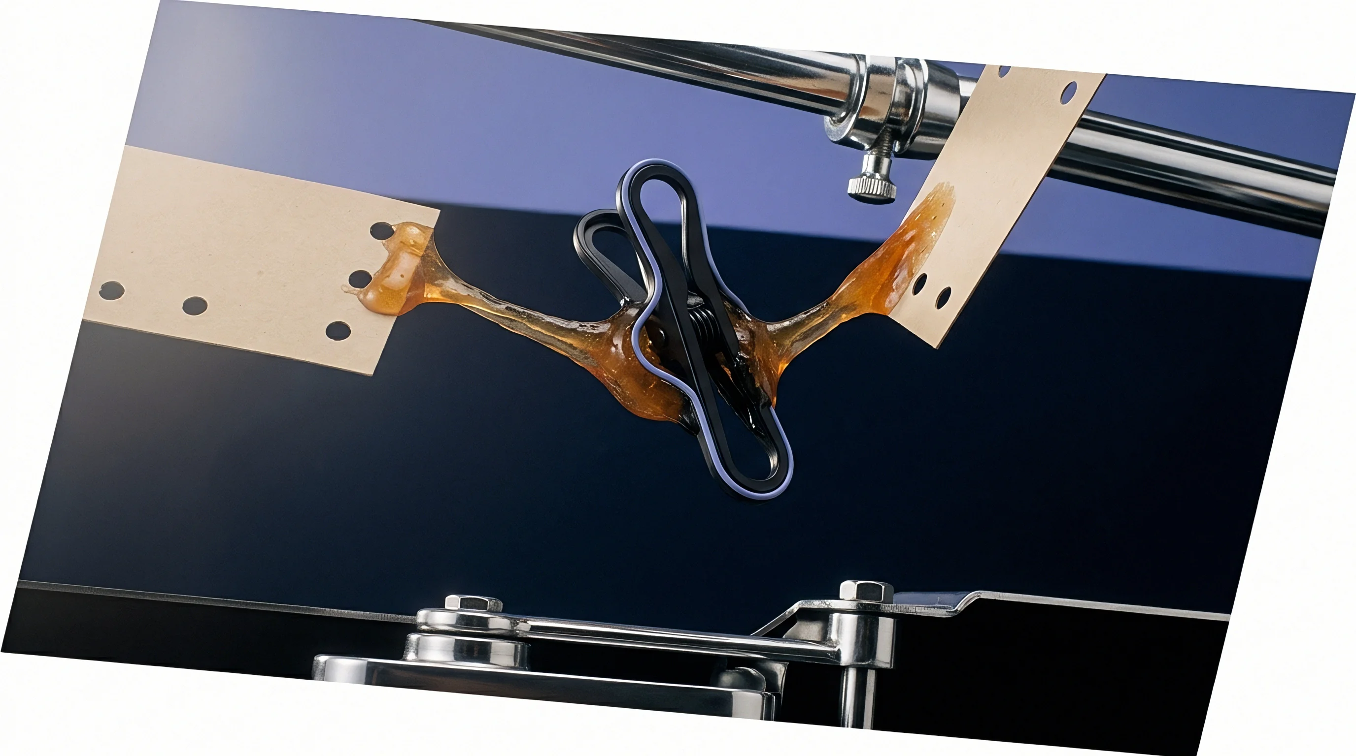
Economic Impact of Splice Failure on Shed Efficiency
Loom shed scheduling depends on overall equipment effectiveness across booked production runs, factoring in availability, performance, and quality yield. High warp break rates drag down availability through frequent stops and hurt performance when technicians throttle machine speed to contain breakage. Slowing a loom from 750 to 600 picks per minute to avoid splice breaks cuts hourly fabric output by 20 percent, driving up landed manufacturing costs per linear meter.
Splice-related fabric defects lead to permanent downgrades under four-point greige inspection. When an end breaks at a splice, adjacent threads can entangle, causing floats, end-out lines, or double ends before the stop motion halts the machine. Manual repairs require weavers to knot or splice replacement threads cleanly; bulky weaver knots risk catching or cutting during downstream shearing and calendering.
Rolls with excessive repair defects drop from First Quality to Second Quality, taking price discounts between 15 and 40 percent.
Evaluating financial losses requires modeling hourly loom operating costs against fabric yield. Modern rapier looms run between 12.00 and 18.00 USD per hour, excluding raw material costs. Frequent stops reduce meters produced per machine hour, shifting the landed cost curve upward.
Loom downtime financial calculations show that an increase of 1.5 warp stops per loom hour raises manufacturing costs by 0.68 USD per finished linear meter on high-density linen fabrics.
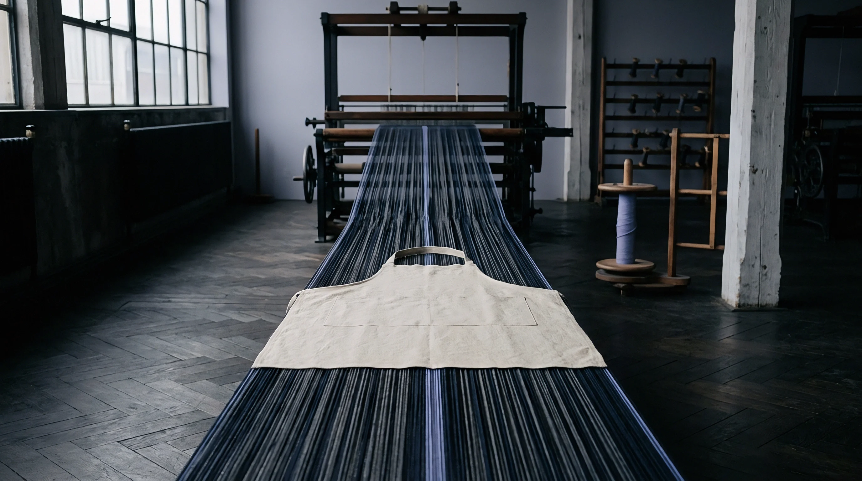
Metre Cost Arithmetic and Machine Capacity Allocation
Landed fabric cost per linear meter includes raw yarn, warping and sizing preparation, hourly loom operating expenses, and finishing yields. Standard weaving equations calculate conversion cost from pick density, loom speed, and operating efficiency. The formula for loom conversion cost per meter is:
Loom Conversion Cost per Meter = (Loom Hour Rate in USD) / ( (Loom PPM / Picks per cm) 60 (Efficiency % / 100) 0.01 )
For a 100 percent linen fabric woven at 22 picks per centimeter on a rapier loom running at 700 picks per minute with a loom hour rate of 15.00 USD, an operational efficiency of 88 percent yields 19.09 linear meters per hour at a conversion cost of 0.786 USD per meter. If splice failures drop efficiency to 72 percent, output falls to 15.61 linear meters per hour and conversion cost climbs to 0.961 USD per meter ~ an added 0.175 USD per meter in pure conversion loss.
Sizing quality and splice compliance are critical cost control checkpoints in textile sourcing. Contracts for fine linen or high-density spun warps should specify maximum allowable warp stops per 100,000 picks. Standard commercial terms cap splice-related breaks at fewer than 1.0 per 100,000 pick insertions.
Lots exceeding this threshold face financial penalties, supplier back-charges for lost loom time, or outright beam rejection.
The testing lab performs dynamic bench audits on incoming warp sample beams before authorizing full production runs. Testing splices on laboratory shed simulators identifies poor wrapper consolidation, incorrect splicing chamber settings, or inadequate sizing coverage before beams reach the weave room floor. Pre-qualification audits protect against weaving delays, cost overruns, and quality disputes, keeping loom capacity utilized and landed fabric margins predictable.