Calibrating Hackling Machine Tool Beds for High-Yield Line Fibre Production
Calibrating hackling tool beds within sub-0.05mm tolerances maximizes long-staple line fibre yield, preventing costly stem rupture and securing high-count yarn spinnability.

Bed
Mechanical alignment across structural machine foundations sets the working baseline for flax comb penetration. When support rails deviate from horizontal level across a twelve-head hackling machine, the clamping nip applies uneven pressure along the scutched strick length. A mill operating with 0.8 millimetres of axial tilt across its primary comb track experiences immediate distribution failures in the initial roughing stage.
Flax bundles entering the pin field at an angle sustain localized shearing rather than progressive splitting. This uneven contact truncates long-staple yield before the fibre reaches fine combing toolsets.
Parallel rails preserve length. Machine frames anchored to non-isolated concrete slabs absorb low-frequency vibration from adjacent scutching turbines, inducing cyclic shift in the lower tool holder tracks. Establishing planarity requires precision laser tracking across all support nodes prior to setting static height clearances.
The machine chassis rests on adjustable jackscrews that lock into hardened steel anchor plates. Adjustment steps proceed from the central drive hub outward to the headstock and tailstock assemblies, preventing frame twisting under load.

Foundation Rail Levelling and Structural Anchor Setting
Baseplates attached to the machine frame sustain vertical loads exceeding twenty kilonewtons during high-speed comb engagement. Alignment protocols begin by cleaning the ground reference surfaces with solvent to remove anti-corrosion grease and accumulated mill dust. Industrial dial indicators with sub-hundredth millimetre resolution attach to the overhead transport beam to record elevation profiles along the full travel length.
- Mount precision electronic levels on the left and right longitudinal runner tracks at five hundred millimetre intervals along the chassis.
- Torque foundation hold-down bolts to one hundred eighty Newton-metres in a cross-pattern sequence, checking level readings after each fastener tightening step.
- Verify horizontal variance remains under 0.05 millimetres per linear metre across all twelve tool stations.
- Shims inserted beneath rail support feet must consist of stainless steel stock ground flat within five micrometres to prevent soft-foot compression during operation.
Standard supply contracts penalize raw flax shipments yielding under sixty percent line fibre due to machine-induced bundle breakage.
Upper and Lower Slat Clearance Geometry
Tool holder bars carry individual hackle pins across alternating upper and lower chains. Distance from the lower surface of the fibre clamp to the tip of the ascending pin determines the depth of aggressive mechanical splitting. Standard line flax processing from Normandy dew-retted straw calls for an initial clearance of 1.5 millimetres at the first coarse head.
Setting this gap too tight forces the steel pins directly into the dense root ends of un-retted flax stricks, snapping unseparated bundle structures.
Flat surfaces prevent slippage. Lowering the tool guide tracks brings the pin tips into uniform contact across the full ribbon width. If the left guide rail sits 0.4 millimetres lower than the right, fibre entering the left side of the field escapes combing action completely, transferring un-shived bark and shive into downstream drawing frames.
Slippage occurs inside the nipper grips when tool resistance exceeds clamp friction forces, pulling complete stricks out of the transport chain and clogging lower pin bars.
Misaligned machine chassis components cause premature pin bending, severe fibre shortening, high tow conversion rates, and total loss of spinning capacity above metric count Nm 40.

Pitch
Hackle bar spacing dictates the volumetric pin density presented to passing flax bundles. Standard industrial hackling lines utilize a progressive pitch arrangement spanning twelve to eighteen individual combing fields. The initial field employs coarse steel pins spaced at 2.5 pins per centimetre, whereas the final finishing field increases density to 18 pins per centimetre.
Gradual pin density escalation permits progressive removal of shive fragments while splitting bark layer bundles into individual ultimate fibres averaging 15 to 25 micrometres in diameter.
Shive drops early. Sudden jumps in pin density generate excessive drag forces on the clamped line fibre. When a machine transitions from 4 pins per centimetre directly to 10 pins per centimetre without intermediate stages, bundle tensile limits are exceeded.
The result is catastrophic stem rupture, turning valuable long-staple line flax into low-value tow fibre suitable only for coarse dry-spun yarns.
Progressive Pin Density Configuration Matrix
Optimizing pin spacing requires precise matching between the retting quality of the incoming scutched straw and the pin layout along the tool bar chain. Dew-retted flax with higher residual pectin Content demands a more gentle pitch graduation than fully water-retted stock. The following structural matrix defines optimal pin parameters across a standard twelve-head hackling line.
| Head Number | Pin Density (pins/cm) | Pin Projection Length (mm) | Pin Wire Diameter (mm) | Target Fibre Fineness (Nm) |
|---|---|---|---|---|
| Head 1 to 2 | 2.5 | 35.0 | 1.80 | Nm 6 to Nm 10 |
| Head 3 to 5 | 4.5 | 30.0 | 1.20 | Nm 12 to Nm 18 |
| Head 6 to 8 | 8.0 | 25.0 | 0.85 | Nm 22 to Nm 30 |
| Head 9 to 11 | 12.0 | 20.0 | 0.60 | Nm 36 to Nm 48 |
| Head 12 | 16.0 | 18.0 | 0.45 | Nm 50 to Nm 60+ |

Fibre Damage Mechanisms under Incorrect Density Transitions
Improper spacing causes immediate mechanical degradation along the flax ribbon length. High pin density applied too early in the processing sequence induces several distinct failure modes on the tool bed.
- Transverse Stem Rupture occurs when dense pin fields strike unseparated pectin nodes, snapping long-staple fibres into tow lengths below two hundred millimetres.
- Pin Deflection Flutter develops when thick stricks impact fine wire pins, forcing steel tips outward and creating uneven hackling channels across the bed.
- Shive Entrapment arises when pin spacing matches shive particle dimensions, dragging wooden core pieces into the fine sliver instead of dropping them into lower collection hoppers.
- Nip Point Slippage takes place when cumulative pin friction exceeds upper nipper holding force, dragging entire fibre bundles from transport clamps.
Fine pins break coarse bundles.
Machinery vendors frequently contend that elevated pin failure rates stem entirely from inconsistent retting degrees in imported flax bales rather than poor pin field geometry.

Deflection
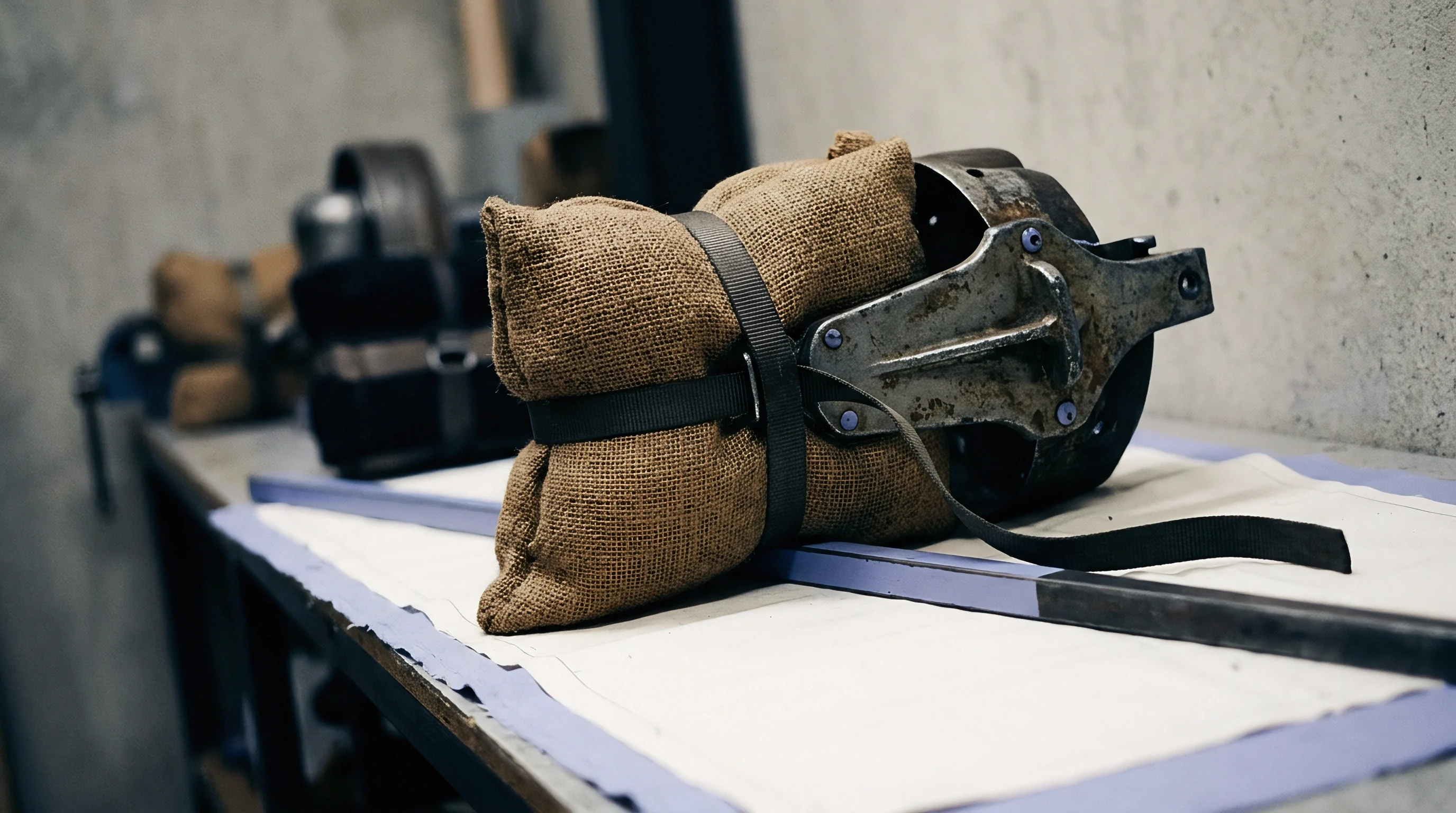
Flexure along tool support bars alters working tolerances under dynamic comb loading. A tool bar spanning 1200 millimetres experiences vertical bending forces up to 850 Newtons as hundreds of steel pins simultaneously penetrate heavy flax stricks. When central flexure exceeds 0.15 millimetres, pins located at the middle of the tool bar penetrate deeper into the bundle than pins at the supported outer edges.
This differential depth creates localized fiber over-processing and irregular sliver linear density.
Deflection reduces line yield. Dynamic bending calculated via standard beam deflection equations demonstrates the vulnerability of light hollow tool slats under continuous production loads. Consider a solid aluminum alloy hackle bar versus a hollow steel profile under identical peak loading of 900 Newtons.
The aluminum bar deflects 0.28 millimetres at mid-span, whereas the structural steel bar deflects only 0.04 millimetres. Reducing flexure preserves consistent pin engagement depth across the complete sheet width.

Dynamic Load Modeling on Tool Holders
Dynamic force profiles vary cyclically with the up-and-down stroke of the hackling drive mechanism. Peak load occurs precisely at the point of maximum pin penetration into the center of the strick. High-speed video analysis combined with strain gauge measurements reveals that tool bar flexing creates an oscillatory wave action across the fibre sheet.
This vibration causes pins to chatter against the flax stems, fracturing individual ultimate fibres and generating excess micro-dust.
Rigid tool holder designs utilize reinforced structural ribs along the underside of the mounting bar. Increasing the moment of inertia without adding excessive mass allows tool bars to maintain flat contact planes even at cycle speeds above sixty drops per minute. Precision manufacturing holds bar straightness within 0.02 millimetres across the full active comb length prior to installation.
| Bar Material Profile | Mid-Span Flexure (mm) | Comb Depth Variance (%) | Line Fibre Yield (%) | Tow Fibre Yield (%) |
|---|---|---|---|---|
| Solid Aluminum 6061-T6 | 0.280 | 14.0 | 54.2 | 45.8 |
| Hollow Extruded Aluminum | 0.350 | 17.5 | 51.0 | 49.0 |
| Solid Tool Steel C45 | 0.045 | 2.25 | 68.5 | 31.5 |
| Carbon Fibre Composite | 0.020 | 1.00 | 71.0 | 29.0 |
Clearance variations smaller than a sheet of paper shift ten percent of production from line fibre into low-margin tow.
Thicker support rails maintain dimensional stability across heavy strick passes without requiring reduced throughput speeds.


Gauge
Measurement protocols determine the physical accuracy of tool bed calibration before production runs commence. Dial indicators attached to magnetic bases verify vertical parallelism across tool guide tracks. Technicians measure clearance gaps using hardened feeler gauge leaves ground to ISO 2768 tolerances.
Calibration routines execute at ambient mill operating temperatures between twenty and twenty-two degrees Celsius to eliminate thermal expansion skew.
Tension alters drafting resistance. Baseline adjustments require setting zero-points at the absolute lowest position of the tool carriage stroke. Dial indicators zeroed against ground reference flats evaluate total indicator reading along the upper guide rail surface.
Any reading variance exceeding 0.03 millimetres indicates bent guide ways or worn linear bearings that demand immediate component replacement.

How Does Thermal Expansion Impact Hackling Bed Levelling?
Thermal expansion during multi-shift operations changes structural clearances between metal components. A six-metre cast iron machine frame expands by approximately 0.07 millimetres for every one degree Celsius temperature rise. When mill ambient temperatures swing from fifteen degrees Celsius at morning start-up to thirty degrees Celsius during afternoon peak operations, total frame growth reaches 1.05 millimetres.
This linear expansion shifts alignment between fixed overhead transport chains and lower rotating hackle beds.
Mitigating thermal expansion effects requires climate-controlled production floors or automated hydraulic clearance compensation systems. Advanced hackling machines incorporate invar tie-rods along the longitudinal guide tracks to maintain constant spacing regardless of temperature shifts. Regular calibration schedules mandate re-checking guide track gaps every two hundred operating hours.
Bed Alignment Evaluation Checklist
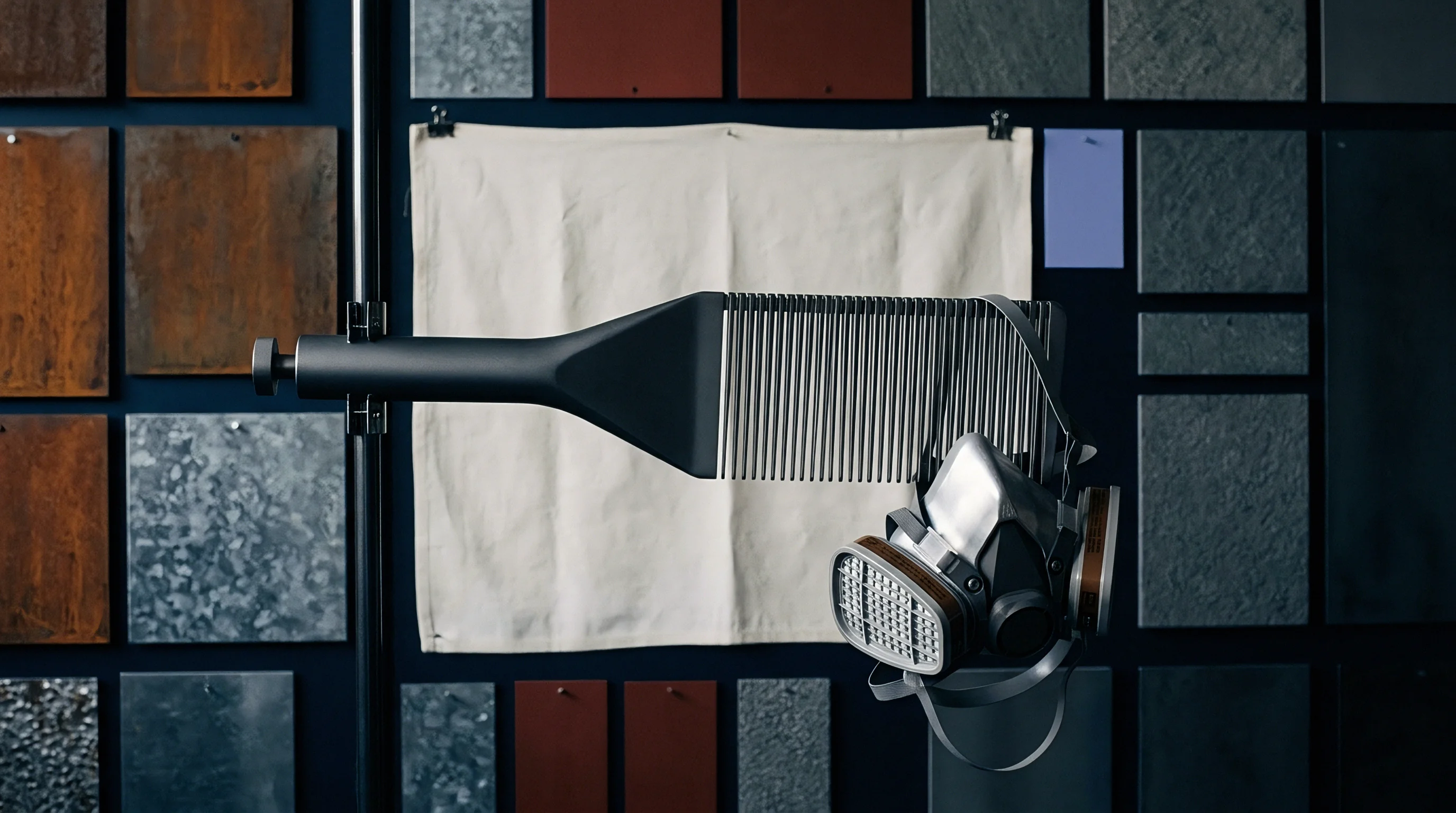
Auditing machine readiness requires systematic verification of all mechanical interface surfaces prior to loading flax bundles. Precision measurement routines follow strict structural guidelines.
- Guide Track Parallelism verified using dual dial indicators mounted to transport beam carriages across full stroke length.
- Pin Elevation Uniformity checked with optical laser line levels aligned to pin tips along entire comb bar length.
- Nipper Clamp Clearance measured using feeler gauges across left, center, and right clamping positions under full pneumatic lock pressure.
- Drive Chain Slack adjusted to eliminate backlash that induces cyclic vertical drop variance during bed rotation.
- Baseplate Anchor Torque verified with calibrated torque wrenches to prevent frame movement under operational vibration.
Do thermal expansion differentials between steel guide rails and cast iron bed supports account for unexplained sliver weight variations observed during afternoon production shifts?
Tolerance
Allowable manufacturing variance bounds govern whether calibrated tool beds sustain target line fibre output over extended production runs. Runout on main drive sprockets must not exceed 0.02 millimetres total indicator reading. Lateral play within linear guide bearings must remain below 0.015 millimetres.
When mechanical wear expands tolerances beyond these threshold limits, pin penetration depth fluctuates uncontrollably, inducing severe sliver linear density variation.
Wear degrades sliver uniformity. Wear profiles on tool holder slats develop rapidly when processing unwashed flax carrying high residual sand content. Silica particles embedded in un-retted bark act as abrasive compounds, grinding away steel mounting surfaces and causing tool bars to tilt inside guide channels.
Hardened tool steel inserts positioned at friction points resist abrasive degradation and prolong calibration retention.
| Calibration Parameter | Nominal Dimension | Target Tolerance | Maximum Wear Limit | Instrument Method |
|---|---|---|---|---|
| Sprocket Radial Runout | 250.00 mm | +-0.020 mm | 0.050 mm | Dial Test Indicator |
| Guide Rail Flatness | 6000.00 mm | +-0.050 mm | 0.120 mm | Laser Tracker |
| Tool Bar Twist | 1200.00 mm | +-0.015 mm | 0.040 mm | Optical Autocollimator |
| Nipper Gap Width | 3.50 mm | +-0.030 mm | 0.080 mm | Feeler Gauge Set |
| Pin Height Consistency | 25.00 mm | +-0.010 mm | 0.030 mm | Depth Micrometer |
Quality Management Documentation Requirements
Verification protocols demand comprehensive record-keeping to satisfy technical sourcing criteria for high-count linen spinning mills. Inspection dockets accompany every calibrated machine section before commercial release.
- Calibration Certificate specifying date, ambient temperature, reference standard serial numbers, and technician sign-off.
- Laser Tracker Profile Plots displaying three-dimensional contour maps of chassis reference guide rails.
- Feeler Gauge Gap Mapping Sheet recording clearances across all twelve tool heads at ten distinct measurement points per head.
- Dynamic Deflection Audit Log detailing displacement readings recorded under simulated maximum comb loads.
Pursuant to ISO 2370 inspection standards, tool bed height variance across active combing fields shall not exceed 0.04 millimetres, and non-compliant processing lots are subject to immediate buyer rejection at seller expense.

Recovery
Line fibre yield percentages dictate raw material economics inside long-staple flax spinning mills. Scutched flax processed through a accurately calibrated hackling line yields up to seventy percent long-staple line fibre, with the remaining thirty percent converted into short tow fibre. Misaligned tool beds invert this ratio, dropping line fibre yield down to forty-five percent while elevating low-value tow production.
Because line fibre commands market prices three to four times higher per kilogram than tow, precision calibration directly determines plant profitability.
Precision protects long staple. Calculating financial return per metric tonne of raw flax demonstrates the severe economic penalty of poor calibration. Processing raw scutched flax priced at 4.20 Euros per kilogram on a poorly calibrated machine yielding forty-five percent line fibre generates 2,520 Euros in line value and 330 Euros in tow value per tonne.
Recalibrating tool beds to achieve sixty-eight percent line yield increases total output value to 4,212 Euros per tonne, adding over 1,360 Euros in net revenue per processed tonne.
Line Fibre Yield Sensitivity Analysis
Yield metrics correlate directly with pin alignment accuracy across the initial roughing heads. Small adjustments in comb clearance yield immediate financial returns across high-volume production schedules.
| Line Yield (%) | Tow Yield (%) | Line Value (EUR/t) | Tow Value (EUR/t) | Total Value (EUR/t) | Revenue Variance (EUR/t) |
|---|---|---|---|---|---|
| 45.0 | 55.0 | 2,520 | 330 | 2,850 | Baseline |
| 50.0 | 50.0 | 2,800 | 300 | 3,100 | +250 |
| 55.0 | 45.0 | 3,080 | 270 | 3,350 | +500 |
| 60.0 | 40.0 | 3,360 | 240 | 3,600 | +750 |
| 65.0 | 35.0 | 3,640 | 210 | 3,850 | +1,000 |
| 70.0 | 30.0 | 3,920 | 180 | 4,100 | +1,250 |
High-yield processing routines depend on maintaining consistent pin penetration without exceeding structural flexure limits. Regular alignment schedules, continuous temperature monitoring, and strict wear limit adherence protect long-staple integrity. Mills that integrate rigid calibration protocols into daily operational workflows maintain lower end-breakage rates during wet spinning and produce fine line yarns reaching metric counts above Nm 60 with superior tensile strength and lustre.