Differentiating Ring Yarn Splice Rupture from Size Film Degradation in Greige Inspection
Distinguish splice rupture from size film failure by inspecting fiber tail slip length versus parent yarn twist retention under optical magnification.
Break

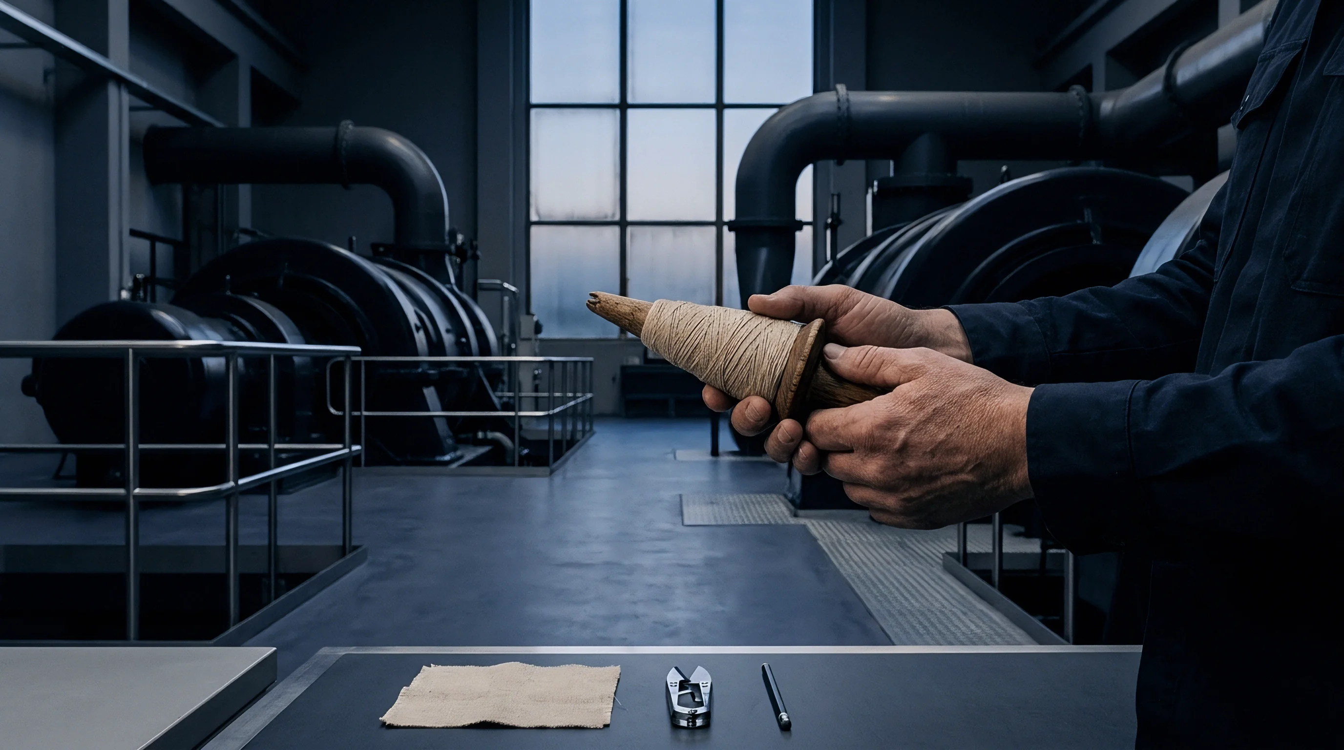
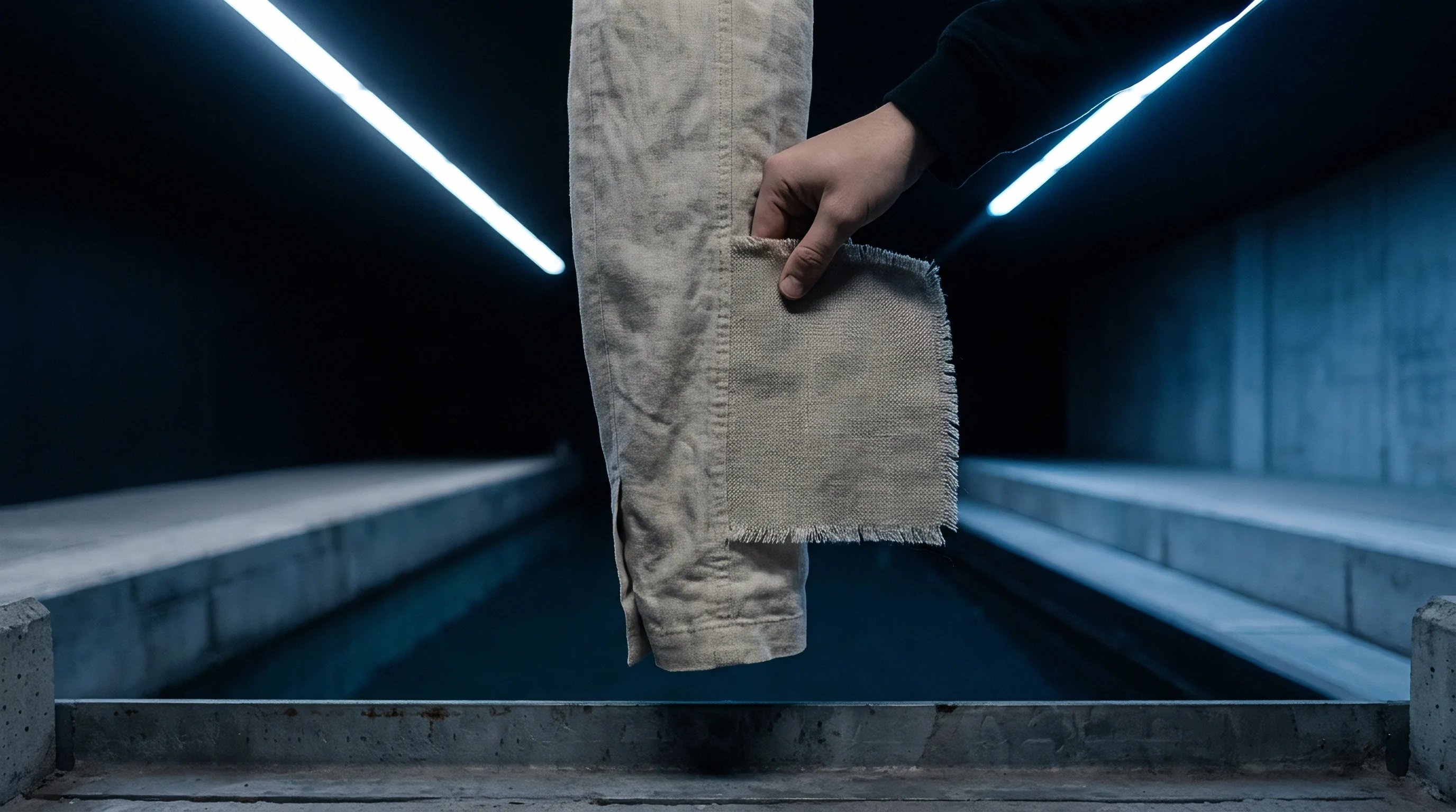
Macro Structural Characteristics on the Greige Inspection Perch
Operators at illuminated grey-cloth viewing tables evaluate yarn discontinuities under ISO 4921 and ASTM D5430 lighting conditions. Visual identification depends on isolating the geometric boundary of the broken end before fabric finishing masks fiber orientation. Ring yarn splice rupture leaves an elongated footprint on the greige surface, appearing as an untangled fiber zone spanning 15 to 25 millimetres ~ matching the mixing chamber length of automatic winder splicers.
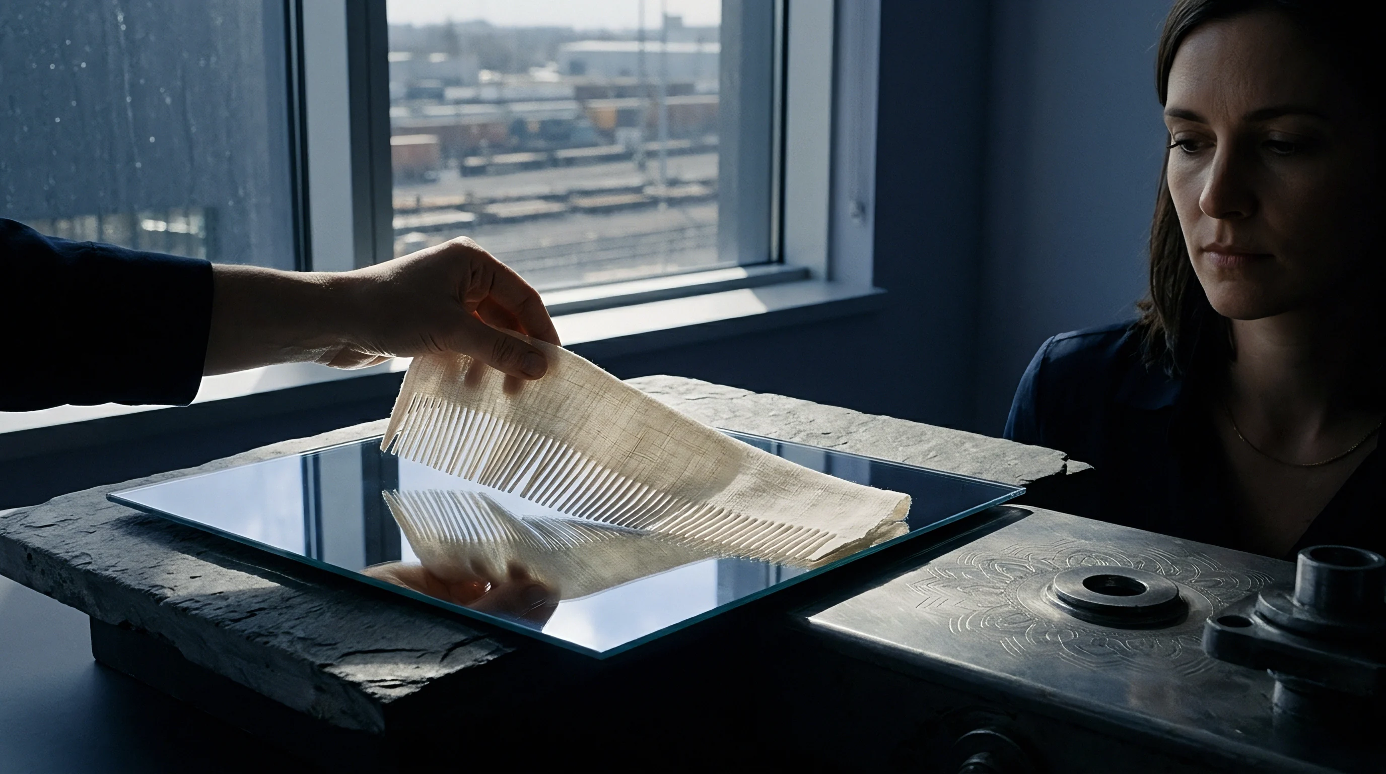
The fiber tips in a ruptured splice show no severe mechanical shear; instead, individual cotton or synthetic staple fibers withdraw longitudinally from the yarn matrix as inter-fiber friction gives way. Turns per metre drop to zero across the splice zone, causing a visible necking down before final separation.
Size film degradation presents a different physical profile on the perch. Yarn failures caused by brittle size fracturing or inadequate encapsulation retain parent yarn twist right up to the fracture point. The break site displays a classic tension snap ~ a broom-head or pencil-point fracture profile rather than an elongated fiber slip zone.
Surrounding the break, the yarn surface shows severe hairiness, loose fuzz, and detached microscopic film flakes. Heavy dust accumulation near the broken end signals binder film breakdown under cyclic abrasive stress in the loom shedding zone.
Distinguishing these two failure modes under 10x magnification prevents misallocating defects during initial greige grading. Spliced yarn pull-outs lack surface size crusting along pulled fiber ends because automatic winder splicing interrupts the continuous size sheath. When pneumatic pressure drops below specified winder thresholds during joining, the fiber tails fail to interlock, creating a weak point that opens under far lower tensile loads than degraded size film can sustain.
A pneumatic splice joint exhibiting less than 75 percent of parent yarn tensile strength fails under beat-up tension spikes exceeding 220 centinewtons per end.
Comparative Geometry of Greige Surface Defects
Visual categorization on the perch requires evaluating physical parameters across consecutive defect sites. Running inspection frames at 15 to 20 metres per minute lets technicians spot localized end breaks, though microscopic confirmation is needed to isolate the mechanical origin.
| Visual Parameter | Ring Splice Rupture | Size Film Degradation | Primary Root Cause |
|---|---|---|---|
| Defect Zone Length | 15 mm to 25 mm elongated region | 1 mm to 3 mm point fracture | Winder chamber length vs loom beat-up snap |
| Twist Density at Break | Zero twist in pulled tail zone | Full parent yarn twist retained | Splice untwisting vs intact yarn sheath |
| Fiber End Morphology | Tapered tail with pulled staple ends | Broom-head or pencil-point shear | Inter-fiber slip vs tensile mass fracture |
| Surface Debris Type | Clean fiber ends, no film flaking | Starch or PVA dust, flaking skin | Mechanical winder error vs size retrogradation |
| Adjacent Warp Condition | Normal hairiness, no abrasion fuzz | High hairiness, surface skinning | Localized splice flaw vs systemic size failure |
Miscategorizing these structural anomalies leads mills to divide corrective actions incorrectly between winding room maintenance and sizing box chemistry. Treating winder splice slip as a sizing film failure prompts unnecessary adjustments to size liquor concentrations, raising chemical costs while leaving mechanical splicing defects unresolved in subsequent production runs.

Adhesion

Pneumatic Fiber Interlock versus Size Encapsulation Mechanics
Ring-spun yarns gain structural integrity through mechanical twist insertion during ring frame drafting and spinning. When automatic winders detect yarn faults, mechanical cutters remove the defect, and pneumatic splicers rejoin the ends with compressed air. Splicing air pressure between 0.50 and 0.65 MPa opens the yarn ends, untwists the fiber tails, and intermingles the loose staple fibers inside a mixing chamber.
The resulting joint relies entirely on inter-fiber friction and geometric entanglement. Water-injection aqua-splicers introduce microscopic liquid droplets to boost temporary fiber cohesion during air blast cycles, optimizing interlock density on high-count cotton warps.
Size film performance depends on chemical bonding and surface encapsulation. Sizing applies a protective polymer shell ~ typically modified starches, polyvinyl alcohol (PVA 1788), or acrylic binders ~ around the yarn core. The size liquor penetrates 10 to 20 percent into the yarn cross-section to anchor the outer film while laying down a continuous elastic coating over surface hairs.
This coating absorbs cyclic extension and abrasive stress from drop wires, heddle eyes, and reed dents on rapier and air-jet looms running above 600 picks per minute.
Splice rupture occurs when pneumatic pressure drops or water injection nozzles clog, preventing full fiber interlock in the chamber. The joint retains little mechanical strength and slips apart under standard warp tension without film fracture. Size film degradation stems from retrograded starch molecules, improper starch-to-PVA ratios, or incorrect squeegee pressures that form a brittle, poorly anchored skin.
When cyclic bending on the loom fractures this coating, loose fiber ends peel back, creating high friction at the drop wires until the yarn snaps under normal shedding tension.
- Chamber pressure starvation resulting in loose fiber entanglement that slips apart at low warp tension thresholds.
- Retrograded starch crystallization creating brittle surface shell micro-fractures during loom reed impact cycles.
- Inadequate tail preparation length causing complete splice pull-out during shed opening extension peaks.
- Excessive softener addition reducing size film cohesion and permitting extensive abrasive fiber peeling.
Shed humidity drops can cause yarn breaks, though splice slip typically stems from winder air pressure variances rather than weave room climate control failures.

Bench

Does Iodine Staining Distinguish Untangled Splices from Size Flakes?
Chemical staining protocols isolate starch distribution across greige defect samples. Applying a 0.01-molar potassium iodide and iodine solution directly to the rupture site produces a vivid blue-violet reaction on starch-based size films. Spliced yarn rupture sites show clear color separation: pulled tail fibers inside the untangled splice region produce no iodine color reaction because splicing occurs before sizing, leaving raw cotton fiber cores that were never penetrated by size liquor.
Size film degradation samples exhibit intense, irregular staining under iodine testing. Fractured ends display thick, cracked bands of blue-violet starch polymer along the yarn circumference, along with detached stained flakes on the fiber shaft. Quantitative evaluation using scanning electron microscopy (SEM) or high-resolution optical microscopy at 100x magnification confirms the spatial boundary of binder materials.
Spliced ends feature intact cut tips from the winder knife alongside pulled fiber shafts, whereas film breakdown sites reveal shattered polymer matrix fragments adhering to abraded fiber walls.
Smooth fiber pull-out tails without cut fiber ends indicate pneumatic mechanical splice slip, whereas shattered yarn boundaries point directly to binder film embrittlement.
Tensile Load-Elongation Curve Analysis
Single-end yarn strength testing under ISO 2062 on automatic tensile test equipment produces diagnostic curves that distinguish mechanical splice failure from film embrittlement. Splice slip yields a multi-peak load-elongation trace or an extended plateau as fibers pull past each other under load, showing low initial tenacity and low work-to-break values. Intact sized yarn affected by film degradation generates a steep initial elastic modulus followed by a sharp, single-stage failure line when the brittle binder shell snaps, triggering instant fiber bundle shear.
| Test Method | Applied Standard | Splice Rupture Diagnostic | Film Degradation Diagnostic |
|---|---|---|---|
| Iodine Reagent Staining | AATCC 20A / ISO 1833 | Unstained fiber cores in tail zone | Dense blue-violet film fracture flakes |
| Single-End Tensile Test | ISO 2062 / ASTM D2256 | Multi-peak curve, pull-out plateau | High initial modulus, steep single drop |
| Scanning Electron Microscopy | ASTM E2015 guide | Smooth pulled fiber shafts, no film | Cracked polymer crust, abraded fibril mass |
| Abrasion Resistance Testing | ASTM D4966 modified | Failure isolated to spliced joint | Systemic shedding along full yarn length |
Standard ISO 4921 purchasing agreements assign full financial credit to the weaver when laboratory tensile curves demonstrate joint pull-out below 70 percent of single-yarn tenacity.


Signals

Drop Wire and Heddle Zone Stop Telemetry
Modern loom monitoring systems record the spatial and temporal distribution of warp stop signals, mapping stops across the harness drop wire banks, heddle frames, and reed zones. Machine telemetry logs every stop motion actuation by warp end number and loom rotation angle. Splice ruptures register as instantaneous end breaks distributed randomly across the warp sheet width, showing no clustering at specific reed dent locations.
When a weak pneumatic splice enters the harness frames, shed opening tension pulls the joint apart cleanly, dropping the harness drop wire immediately during shedding between 60 degrees and 120 degrees of loom rotation.
Size film degradation stops generate distinct localized clusters on loom telemetry dashboards. Repeated stops at specific heddle frames or high-density reed sections point directly to localized abrasive stress exceeding size film elasticity. Flaking size film creates high friction as yarn slides through drop wire eyes, causing gradual end slackening before the drop wire contacts the electrical contact bar.
Telemetry logs show these stops occurring predominantly during shed closing and beat-up, between 300 degrees and 360 degrees of the rotation cycle.
- Isolate the stopped warp end immediately at the drop wire bank to avoid disturbance of the break boundary.
- Measure the distance from the fell of the cloth to the break location using a millimeter scale.
- Cross-reference the measured distance against the harness frame back-rest cycle distance to identify the active loom zone.
- Examine the adjacent warp ends for accumulated starch dust or loose fiber tails under 10x illuminated loupe.
Warp breaks recorded systematically at the drop wire bank trigger automatic lot re-inspection under ASTM D5430 when defect frequency exceeds 1.5 stops per 100,000 pick metres.

Spatial Analysis across Reed Width and Loom Zones
Distinguishing localized mechanical splice stops from broad sizing deficiencies requires analyzing the frequency distribution of warp breaks per loom hour. Splicing failures remain directly proportional to the number of winder bobbin joins in the warp beam set, holding constant throughout beam unwinding. Size film failure rates escalate as loom shed temperatures rise and relative humidity drops below critical thresholds, accelerating starch film embrittlement over multi-shift production runs.
Whether real-time acoustic sensors on air-jet looms can distinguish the sound signature of a pulling splice tail from a snapping sized yarn end without manual perch verification remains open for shed operators.

Audit
Four-Point Grading System Point Allocations
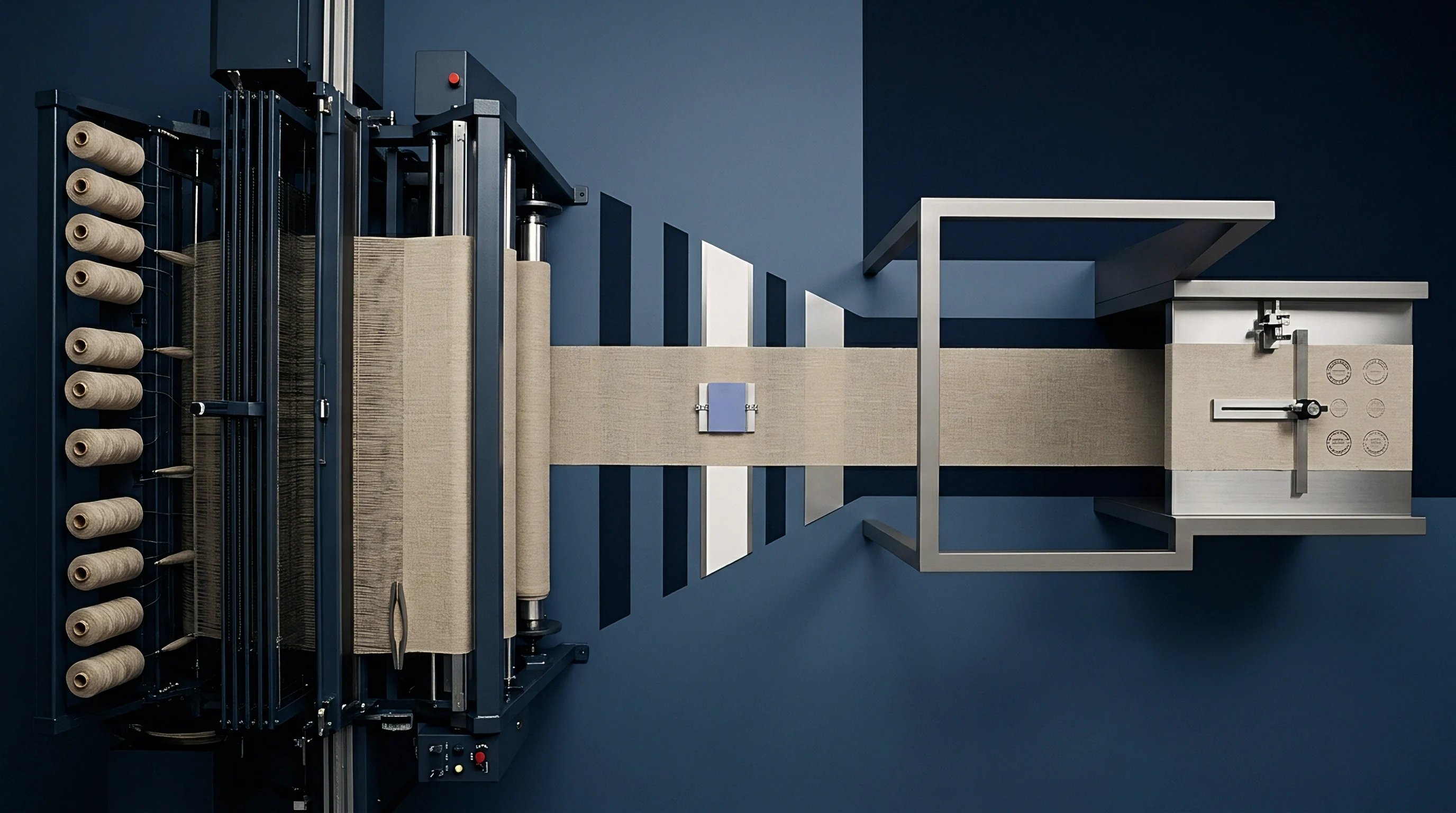
Greige fabric inspection standards under ASTM D5430 assign penalty points based on defect length along the warp direction. Individual broken ends repaired by weaver knots or left as short warp floats receive specific point deductions depending on fabric end use and customer specifications. Splice ruptures that pull apart cleanly without tearing adjacent ends incur a 1-point or 2-point penalty if the resulting thin spot stays under 130 millimetres.
Size film degradation frequently triggers systemic multi-end breaks, warp streaks, or heavy balling-up of loose fibers behind the reed. When abraded size film peels back along adjacent ends, multiple yarns roll together to create heavy warp floats or multi-end breakouts exceeding 230 millimetres. Scoring assigns 4 points to these multi-end failure zones.
Reaching or exceeding 28 penalty points per 100 square yards downgrades the fabric roll from First Quality to Second Quality, imposing direct commercial losses on the weaver.
Worked calculations establish clear financial liability between yarn suppliers and warping houses. Consider a 50,000-metre order of 100 percent cotton 2/1 twill fabric, 160 cm greige width, 120 g/m² cloth weight, running on high-speed rapier looms at 550 picks per minute. Total warp stop rates attributable to yarn defects govern the financial debit calculation:
Assume a baseline weaving cost of 18.50 USD per loom hour with 4,800 total warp ends. Standard production books 0.80 warp stops per 100,000 pick metres. A lot suffering from severe pneumatic splice rupture demonstrates 3.20 stops per 100,000 pick metres, adding 120 loom stoppages across the order run.
At 2.5 minutes of repair time per stop, downtime consumes 5.0 loom hours, amounting to 92.50 USD in direct lost weaving efficiency.
If inspection reveals 14 downgraded rolls from 4-point penalty accumulations caused by multi-end size abrasion, grey cloth value drops 30 percent from a first-quality price of 2.40 USD per metre down to 1.68 USD per metre. Across 1,400 metres of downgraded cloth, the commercial loss equals 1,008.00 USD. Attributing this loss accurately depends on bench test proof isolating size film embrittlement from winder splice pull-outs.
- Point penalty cap setting maximum allowable four-point score at 28 points per 100 square yards prior to roll downgrade.
- Spinning mill credit covering direct loom downtime costs when splice failure exceeds three percent of warp breaks.
- Sizing house debit enforcing full beam replacement charges upon proof of starch retrograde film failure.
- Greige claim threshold requiring notice within fourteen business days of roll delivery to the customer frame.
When splice pull-out accounts for more than half of all warp stops, the spinning mill bears the cost of grey cloth downgrades.
Squeeze
Winder and Sizing Room Machine Calibration Parameters
Eliminating splice rupture requires systematic maintenance of automatic winder splicing heads. Splicing air line pressure must remain stabilized between 0.60 and 0.65 MPa at the winder manifold, with filtration units removing moisture and compressor oil down to 0.01 microns. Tail preparation dials require calibration to maintain tail lengths between 18 and 22 millimetres for 30s Ne cotton yarns.
Calibrating aqua-splicer water injection volumes to 0.02 millilitres per splice cycle at controlled water temperatures optimizes fiber wetting, preventing dry slip without causing saturation that inhibits pneumatic blending.
Sizing room process control focuses on squeegee roller pressure, size box temperature, and drying cylinder thermal gradients. High-pressure squeegee rolls operating at 20 to 35 kN squeeze load deliver precise pick-up control, maintaining target dry size pick-up between 11 and 13 percent for 100 percent cotton warp yarns. Holding size box temperatures steadily at 85 to 90 degrees Celsius prevents starch retrogradation, while stepping drying cylinder temperatures down from 130 degrees Celsius on the first cylinder group to 90 degrees Celsius on the final group prevents thermal baking and film embrittlement.
| Process Stage | Target Parameter | Cotton Ring 30s Target | Poly-Cotton 45s Target |
|---|---|---|---|
| Winder Splicing Chamber | Compressed Air Pressure | 0.60 MPa to 0.65 MPa | 0.65 MPa to 0.70 MPa |
| Winder Tail Prep Unit | Stripped Tail Length | 18 mm to 22 mm | 16 mm to 20 mm |
| Size Box Squeegee Roll | Nip Squeeze Load | 22 kN to 28 kN | 28 kN to 35 kN |
| Size Liquor Box | Refractometer Brix Solids | 12 percent to 14 percent | 10 percent to 12 percent |
| Drying Cylinder Group 1 | Surface Temperature | 125°C to 130°C | 115°C to 120°C |
Refractometer readings taken at two-hour intervals maintain size solids concentration within the specified target range.
Regular maintenance of rubber squeeze roll hardness, measured between 65 and 70 Shore A, prevents uneven wet pick-up across the warp beam width. Integrating automated refractometer monitoring inside the size recirculation line maintains chemical solids concentration within a tight 0.5 percent tolerance band. Correcting winder pneumatic pressure and size box squeegee loads reduces greige warp stops, producing clean inspection rolls that comply with international grey fabric quality standards.