Relay Nozzle Firing Angles for Staple Linen Filling Insertion
Optimizing relay nozzle angles to 8 degrees toward the reed base stabilizes staple linen yarn flight and prevents tip unraveling during high-speed air-jet weaving.


Blast
Main Jet Velocity Profiles and Drag Forces
Compressed air entering the insertion channel at 0.35 MPa reaches supersonic speed near the orifice before dropping to subsonic levels within thirty millimetres. Because flax fibers resist axial extension, the high bending stiffness of wet-spun linen yarn resists initial acceleration, demanding significantly higher momentum transfer from the pneumatic stream than smooth filament yarns require. Although the main nozzle supplies the primary thrust to pull thread off the feeder drum, aerodynamic drag along the yarn body decays exponentially as the insertion front moves across the loom width.
Pneumatic momentum transfer depends on yarn surface roughness and linear density. A 100 percent staple flax yarn measuring 26 Nm (38.4 tex) possesses prominent surface hairs that increase aerodynamic drag in high-velocity zones, where excess kinetic energy at the pick head causes fiber detachment and tip unraveling. Main nozzle blowing pressure configured above 0.40 MPa shears outer fibers from the core bundle, generating fly waste that clogs the reed tunnel.
The velocity differential between the air stream and the yarn tip must remain within precise thresholds to preserve thread integrity.
| Yarn Linear Density (Nm / tex) | Main Nozzle Pressure (MPa) | Sub-Nozzle Line Pressure (MPa) | Initial Drag Force (cN) | Terminal Velocity (m/s) |
|---|---|---|---|---|
| 14 Nm (71.4 tex) | 0.42 | 0.38 | 18.5 | 42.0 |
| 26 Nm (38.4 tex) | 0.35 | 0.32 | 14.2 | 48.5 |
| 36 Nm (27.7 tex) | 0.28 | 0.26 | 11.0 | 54.0 |
| 52 Nm (19.2 tex) | 0.22 | 0.21 | 8.4 | 58.2 |
Staple Linen Friction Dynamics in Air Channels
Surface friction along a profiled reed channel creates an asymmetric boundary layer that draws the yarn toward the reed teeth, while high bending stiffness retards head flight. When staple linen travels through open air without lateral support, the yarn tip drops below the optical sensor axis, triggering false warp stops. Relay nozzles maintain pick velocity by injecting auxiliary air pulses that compensate for friction losses without increasing yarn tension.
A supply line pressure below 0.28 MPa at 26 Nm count drops tip velocity below forty metres per second and causes mid-shed bucking.
Positioning sub-nozzles along the insertion path requires balancing air consumption against thread flight stability. Coarse linen counts require higher pneumatic force to overcome mass inertia, yet excess pressure bends the pick head into the upper warp sheet as static tension drops. The angle of air discharge from each sub-nozzle dictates whether the yarn stays centered in the profiled reed channel or collides with reed blades.
Incorrect nozzle alignment causes severe mechanical defects in grey fabric. When the air stream pushes staple linen against upper or lower warp ends, fiber friction creates localized tension spikes, resulting in broken picks, loose loops on the selvedge, or premature weft stoppages that drop loom efficiency below seventy percent.
Kinematics
Crank Angle Firing Sequences across Loom Width
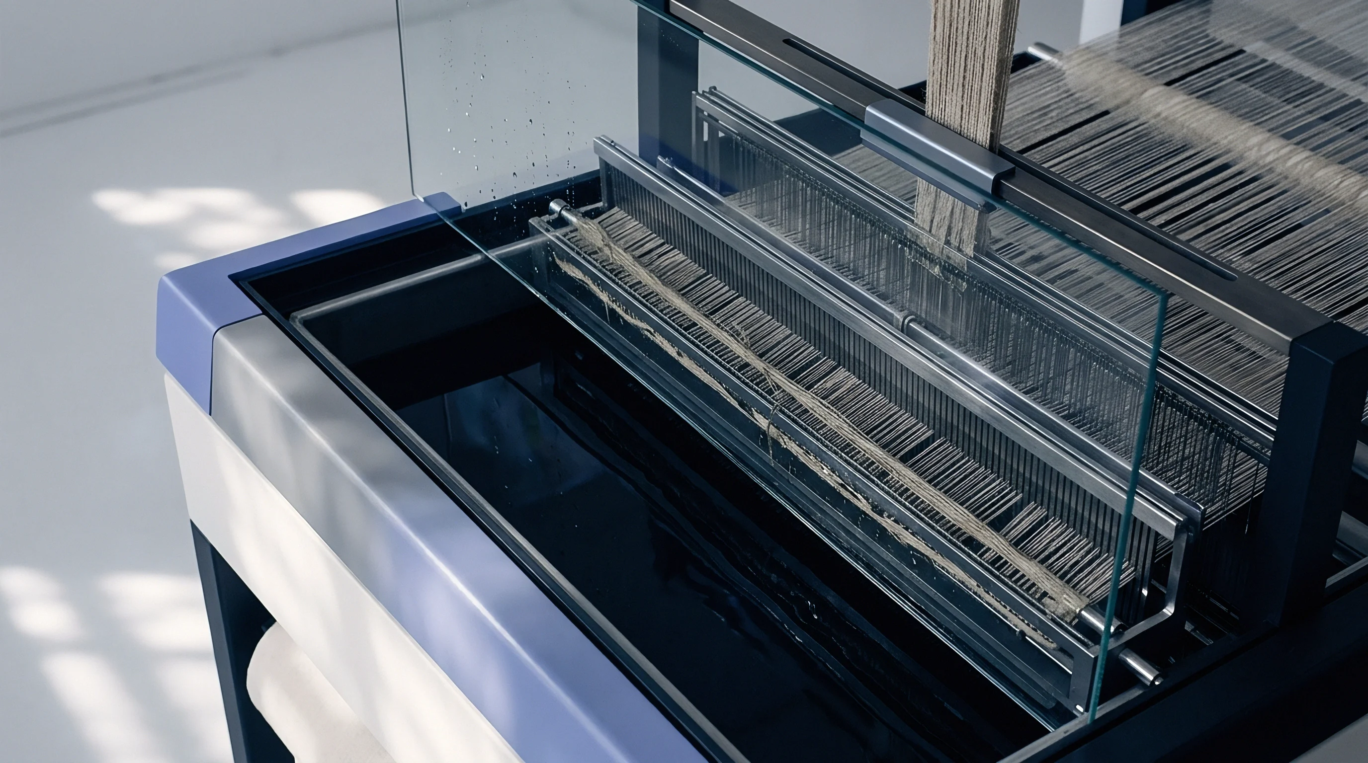
Timing the opening and closing of solenoid valves relies on main shaft position, measured in degrees of crank angle. Insertion starts around 85 degrees, when the shed opens sufficiently to clear the incoming yarn head. The main nozzle energizes first, followed by sequential groups of two or three relay nozzles positioned at uniform intervals across the reed space.
Each group remains open for forty to sixty degrees of crank rotation to hand off the pick head to the downstream air stream.
- Position the main nozzle valve activation switch at 82 degrees crank angle to establish initial pneumatic force before filling release.
- Set the first relay nozzle valve cluster to open at 105 degrees, overlapping the main jet blow duration by ten degrees of mainshaft rotation.
- Advance downstream relay nozzle groups in increments of twenty-five degrees, maintaining a constant valve open duration of fifty-five degrees per block.
- Calibrate the final relay nozzle group to cease firing at 255 degrees, coinciding with the arrival of the pick head at the right-hand optical sensor.
- Adjust the catch-selvedge tensioner engagement angle to 270 degrees to hold the trailing thread end prior to reed beat-up.
Acceleration Offsets for Low Elongation Fibers
Flax fibers feature total elongation values between 1.5 and 2.2 percent, offering minimal elasticity under dynamic loads. Sudden acceleration impulses from mis-timed sub-nozzles snap the filling yarn at the main nozzle exit. The delay interval between adjacent sub-nozzle valve actuations must match the flight speed of the pick head across the weaving width; if a downstream nozzle fires too early, backpressure retards yarn flight, whereas late firing causes the pick to lose momentum and droop.
Relay valve open duration must scale linearly with loom width to prevent filling deceleration before arrival at the right selvedge.
High-speed video analysis confirms that staple linen yarn decelerates rapidly when air velocity drops below thirty-five metres per second. Firing overlapping air streams from consecutive sub-nozzle banks preserves thread straightness. The angular offset between valve open points typically ranges from 20 to 30 degrees of crank rotation on a 190-centimetre loom running at 550 picks per minute.
Precision in valve actuation avoids filling bucking and prevents tail formation inside the reed channel.
Excessive overlap between valve firing groups increases total compressed air usage without improving pick arrival times. Setting relay nozzle firing windows precisely ensures maximum energy transfer while keeping volumetric air consumption within sustainable shed budgets.
Profile
Reed Tunnel Geometry and Air Wall Friction
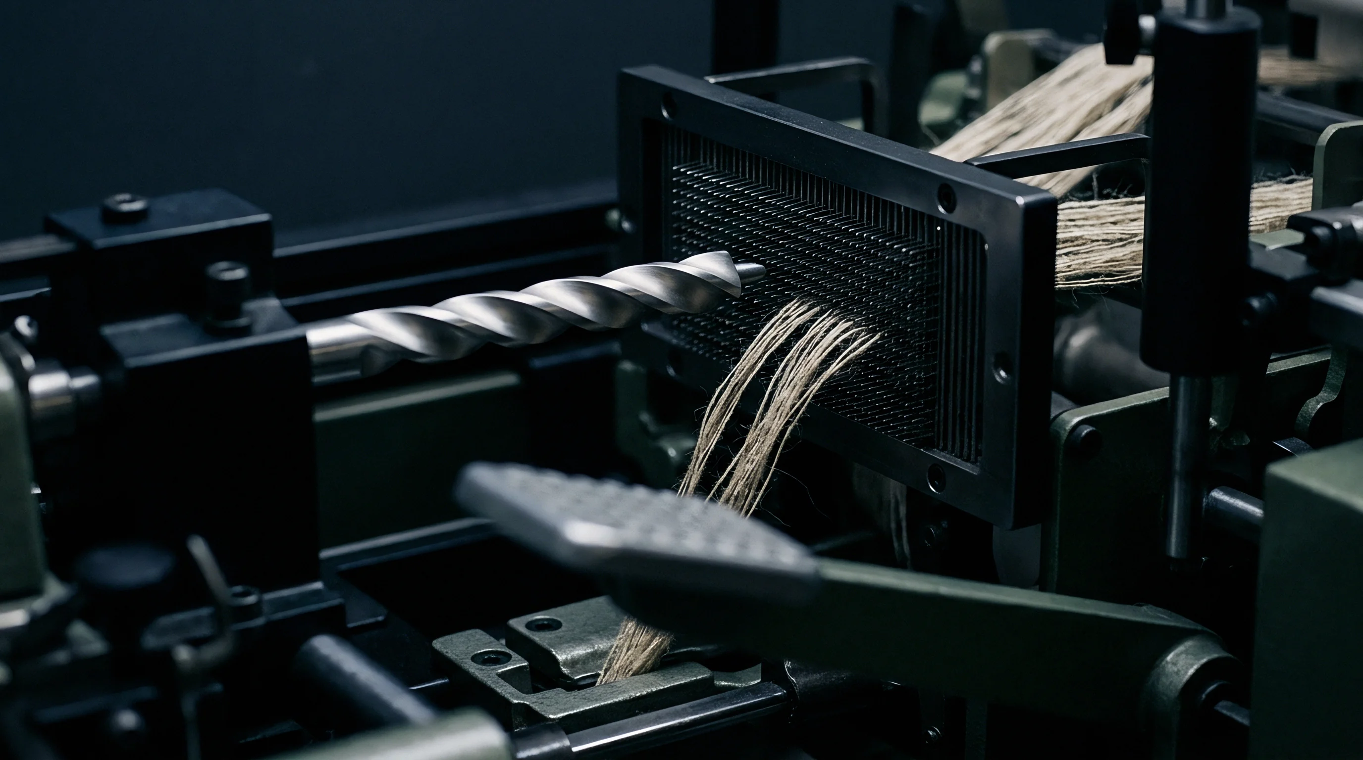
Profiled reed blades construct a pseudo-enclosed channel that retains the moving air column across the weaving width. The cross-sectional dimensions of the reed tunnel dictate the velocity decay rate of the air jet. Flax fibers shed short fibrils into this channel, altering wall surface roughness during continuous operation and causing localized turbulence that destabilizes yarn trajectory.
To control flow direction inside the tunnel, technicians adjust the inclination angle of the sub-nozzles relative to the reed face. Inclining nozzles slightly toward the back of the profile pushes the yarn against the solid aluminum channel back, using air pressure to stabilize thread flight. An angle directed too far out toward the open shed space allows air to escape between reed wires, losing pressure and dropping yarn speed.
- Relay nozzle pitch spacing must be restricted to 65 millimetres for staple linen yarns coarser than 20 Nm to prevent pick sagging between blowing points.
- Sub-nozzle inclination angle requires precise setting at 8 degrees toward the reed profile base to contain hairy staple fibers within the guided air stream.
- Blowing outlet orifice diameter must equal 1.2 millimetres to generate a concentrated air core capable of moving heavy linen counts without excessive air expansion.
- Reed profile height opening must measure no less than 11.5 millimetres to provide vertical clearance for flax slubs passing through the air guide path.

Relay Nozzle Divergence Pitch Variations
Sub-nozzles mounted along the reed rail feature single-hole, multi-hole, or conical diffuser tips. Multi-hole nozzles disperse air over a wider cross-section, reducing peak impact pressure on the yarn while maintaining high volumetric flow. Single-orifice nozzles deliver a concentrated high-velocity core that penetrates thick linen yarn bundles but increases the risk of fiber fraying.
Conical outlets balance jet spread and core velocity for medium linen counts.
| Yarn Count Range (Nm / tex) | Nozzle Tip Configuration | Mounting Pitch (mm) | Horizontal Pitch Angle (°) | Vertical Tilt Angle (°) |
|---|---|---|---|---|
| 10 – 18 Nm (100 – 55.5 tex) | Multi-Hole (7 Hole) | 55 | 9.5 | 2.0 |
| 19 – 30 Nm (52.6 – 33.3 tex) | Conical Single Hole | 65 | 8.0 | 1.5 |
| 31 – 45 Nm (32.2 – 22.2 tex) | Single Hole Standard | 70 | 7.0 | 1.0 |
| 46 – 70 Nm (21.7 – 14.2 tex) | Single Hole Fine | 85 | 6.0 | 0.5 |
Standard commercial supply contracts reject greige rolls containing more than two filling stops per one hundred thousand meters of inserted yarn attributable to air jet misdirection.
Altering the distance between sub-nozzles changes both air consumption and thread control. Fine linen yarns allow wider pitch spacing because low fiber mass requires minimal air force to sustain velocity, whereas coarse flax counts demand tighter spacing to prevent the yarn body from falling out of the high-speed air stream. Setting pitch spacing without accounting for yarn linear density yields high stoppage rates and inconsistent fabric density across the selvedges.
While factory baseline configurations are often intended as universal setups across yarn types, staple linen in practice requires custom mounting blocks and adjusted angular pitch settings to manage fiber stiffness and surface hairiness without causing constant pick stops.

Disruption
Flax Slub Drag and Micro-Shed Interferences
Irregular mass distribution remains an inherent trait of wet-spun flax yarns. Thick places, slubs, and neps increase yarn cross-sectional diameter by up to two hundred percent over short lengths. When a slub enters the profiled reed tunnel, its enlarged cross-section experiences sudden air drag forces that accelerate the yarn segment faster than the rest of the pick.
Slubs passing through the reed profile alter local aerodynamic drag and pull trailing thread segments out of alignment.
This localized acceleration causes tailing and loops: the heavy slub section pulls ahead, creating slack in the lower-density yarn segment immediately behind it. If warp ends inside the shed drop slightly due to loose harness cords or improper warp tension, the slack filling loop catches on individual warp threads, generating tension spikes that shear staple fibers. The resulting obstruction stops the pick mid-flight, causing a short pick fault that requires operator intervention.
- Slub tip wedging occurs when an oversized yarn defect wedges between reed wires, snapping the pick under main nozzle pressure.
- Micro-shed hair trailing arises when protruding flax fibers entangle adjacent warp threads, pulling the filling out of the pneumatic channel.
- Kink formation results from downstream air pressure blowing back over a slack yarn segment created by a high-drag slub.
- Sensor blinding happens when fly waste released from passing slubs collects on the optical pick detector lens, triggering false filling stops.

Unraveling Tip Entanglements in Relay Jet Streams
Staple linen yarn twist drops near the leading tip as air shear unwinds surface fibers during flight, where peak impact pressure causes tip splay. These unwound fibers spread outward into a brush-like tail that increases aerodynamic drag and catches on warp ends at the shed boundary. When the yarn head splays, the arrival signal at the far optical sensor spreads over time, preventing clear digital detection.
To mitigate tip unraveling, technicians adjust the firing angle of the first two relay nozzle groups. Angling the initial nozzles slightly parallel to the yarn path reduces perpendicular impact force on the leading head, suppressing fiber splay. Lowering line pressure on the first valve group reduces peak air shear while preserving sufficient velocity to carry the yarn body past the critical entry zone.
Unanswered questions persist regarding the dynamic interaction between sizing starch formulations and air shear rates at the pick head. Sizing agents increase yarn surface smoothness and bind surface fibers to the core bundle, yet stiff coatings reduce yarn flexibility, raising the risk of brittle fractures when high-velocity air impacts the pick tip. Sourcing evaluations continue to examine whether flexible polymer sizing additives can eliminate tip splay without demanding higher compressor pressures across long loom widths.


Audit

Where Does Air Consumption Spike in Linen Sheds?
Compressed air usage rises sharply when operators widen relay nozzle firing windows to compensate for irregular pick arrival times. Increasing the firing arc from 45 to 65 degrees of crank angle across eight sub-nozzle groups elevates air demand by thirty-eight percent per loom. Leaks at sub-nozzle tube connectors, worn solenoid seals, and misaligned valve manifolds further inflate pneumatic losses, forcing air generation plant capacity to its operational limit.
Measuring pressure drop along the main air distribution rail identifies localized flow bottlenecks across long looms. A pressure differential exceeding 0.03 MPa between the regulator block and the final sub-nozzle valve indicates inadequate supply piping diameter or restrictive fittings, destabilizing the steady line pressure required for direct insertion.

Stroboscopic Verification of Pick Arrival Times
Verifying thread flight path dynamics requires synchronized stroboscopic illumination triggered by the loom encoder. Technicians align the strobe pulse with specific crank angles to observe yarn positioning inside the reed channel during flight, ensuring late arrivals do not trip optical sensors. Adjusting sub-nozzle horizontal and vertical angles while viewing flight alignment under strobe light keeps the yarn centered throughout the insertion stroke.
| Observed Flight Deflection | Root Cause Alignment Fault | Correction Procedure | Target Flight Angle (°) |
|---|---|---|---|
| Yarn strikes upper reed profile wall | Vertical tilt angle set too high | Lower sub-nozzle tilt bracket by 0.5 to 1.0 degree | 1.0 – 1.5 upward tilt |
| Pick head drifts out of channel | Horizontal angle directed too outward | Rotate nozzle base toward reed base by 1.5 degrees | 8.0 toward profile base |
| Yarn tip splay and fiber fraying | Excessive air impact from first jet group | Reduce line regulator pressure by 0.04 MPa | 0.28 – 0.32 MPa line force |
| Wavy yarn trajectory between jets | Sub-nozzle pitch spacing too wide | Move nozzle mounts closer; reduce pitch to 60 mm | 55 – 65 mm pitch distance |
- Mount the digital alignment gauge directly onto the reed rail base, referencing the flat surface of the bottom shed line.
- Set sub-nozzle horizontal inclination using the protractor attachment, locking the mounting bolt once the target angle shows on the display.
- Verify vertical tip height relative to the profile center line using an optical feeler gauge, maintaining a two-millimetre clearance from the channel floor.
- Check solenoid valve response time using an inline pressure transducer connected to a digital oscilloscope, rejecting valves with opening delays over three milliseconds.
- Execute a dry air blow test without yarn to measure air jet dispersion using a pitot tube positioned fifteen millimetres downbeam from each nozzle orifice.
International standard ISO 5247-3 specifies methods for determining power consumption in air-jet weaving machinery, declaring that all volumetric air flow measurements must be normalized to standard temperature and pressure conditions (20 degrees Celsius and 101.3 kPa). Compliance with this standard alters how mill energy efficiency is calculated on grey linen production, penalizing facilities that rely on elevated line pressures to conceal mechanical alignment errors.
Ledger
Air Compressor Kilowatt Allocation per Woven Metre
Electrical power consumed by air compressors represents the single largest variable operating expense in air-jet linen weaving. A modern screw compressor requires approximately 0.12 kilowatt-hours to generate one cubic metre of compressed air at 0.6 MPa. Insertion of a single filling pick across a 190-centimetre reed width consumes between 0.0025 and 0.0040 cubic metres of air, depending on yarn count, nozzle pitch, and firing window duration.
Calculating energy cost per metre of fabric combines loom speed, picks per centimetre, pick insertion air volume, and compressor electrical efficiency. For a fabric construction with 20 picks per centimetre running at 500 picks per minute, the loom produces 15 metres of greige cloth per hour. Misalignment of sub-nozzles that forces line pressure upward by 0.05 MPa increases air generation power draw by eight percent, directly lowering the gross operating margin per loom hour.
| Reed Width (cm) | Loom Speed (PPM) | Air Demand (m³/min) | Compressor Power (kW) | Efficiency (%) | Air Cost per Metre ($) |
|---|---|---|---|---|---|
| 190 | 550 | 0.85 | 6.12 | 88.5 | 0.068 |
| 230 | 480 | 1.10 | 7.92 | 85.0 | 0.098 |
| 280 | 420 | 1.42 | 10.22 | 81.2 | 0.142 |
| 340 | 360 | 1.85 | 13.32 | 76.4 | 0.210 |

Sourcing Mill Machine Setting Acceptance Protocols
Procurement specifications for staple linen fabrics must incorporate machine setup parameters alongside physical cloth standards like mass per unit area and tensile strength. Sourcing contracts that define maximum allowable compressed air pressures and mandated sub-nozzle firing angles protect buyers from purchasing cloth produced under high-stress insertion conditions, which weaken yarn structure and lead to elevated pilling and reduced seam fatigue strength in finished garments.
A comprehensive technical dossier mandates mill reporting of exact sub-nozzle inclination angles, pressure settings, valve timing windows, and ambient humidity levels inside the weaving shed. Maintaining relative humidity between 68 and 75 percent in the loom shed keeps flax moisture regain near eight percent, preserving fiber flexibility and reducing friction during air insertion. Technical qualification audits inspect these settings against approved production benchmark sheets before authorizing bulk production runs.
Quantifying landed fabric cost demands including pneumatic energy tariffs, loom stop frequencies, and greige repair labor overhead. When a mill operates air-jet looms with sub-nozzles inclined beyond optimal geometric limits, higher stoppage rates increase manual mending costs for broken picks and loose loops. Factoring these operational variables into supplier evaluation matrices prevents premature commitments to facilities that achieve high speed only by compromising yarn physical performance.