Quantifying Fabric Bending Hysteresis Metrics in Pure Bending Laboratory Testing
Pure bending laboratory testing isolates fabric bending rigidity and hysteresis width from gravitational shear, yielding precise metrics for cloth tailoring.


Flex
How woven fabrics deform under bending loads dictates their hand, drape, and tailorability. Evaluating flexural behavior properly requires isolating pure moment from secondary forces. Standard cantilever methods, such as fixed-angle slanting plane tests, mix bending with variable shear and gravity-driven axial tension.
As a cloth sample sags under its own mass, curvature varies continuously along the unsupported span from the clamp to the free end. This non-uniform curvature invalidates simple beam equations, making it impossible to extract true material constants directly from measured bend lengths.
Pure bending testing eliminates gravity sags and shear gradients. Applying equal and opposite end couples to a flat cloth strip establishes uniform curvature across its entire active length. Every cross-section experiences identical bending moments, producing a true circular arc.
Testing woven structures in a controlled pure moment environment reveals the baseline stiffness and recovery mechanics of yarn intersections without mechanical artifacts.

Mechanics of Pure Bending Curvature
Standard cantilever tests introduce a spatial shear gradient along the specimen. In pure bending rigs, drive chucks apply pure torque at the boundaries. Curvature K is defined as the reciprocal of the bending radius R along the specimen centerline.
Moment sensors directly measure applied torque M per unit cloth width. Plotting moment against curvature over a complete forward and reverse rotation cycle yields a closed hysteresis loop. The slope of this curve in the linear region defines bending rigidity B per unit width ~ the stiffness parameter governing resistance to curvature under external forces.

Elimination of Shear and Gravity Gradients
Equal and opposite end couples produce a constant internal bending moment across the unclasped span. Removing vertical supports or gravitational overhangs isolates structural response from fabric mass. Heavy, dense fabrics and light, sheer materials can be measured on identical curvature scales without weight distorting the geometry.
Shear forces alter apparent bending resistance by causing warp and weft yarns to slide past one another prematurely. Eliminating shear isolates pure flexural rotation from inter-yarn trellis deformation, yielding clean constitutive parameters needed for automated cloth modeling in cutting and sewing operations.
At 20 degrees Celsius and 65 percent relative humidity, 100 percent linen plain weave cloth exhibits a bending rigidity of 0.42 cN cm squared per cm under pure curvature loading.
Accurate curvature measurement depends on holding active specimen length constant during grip rotation. Modern testing instruments use optical encoders and zero-backlash drive gears to preserve exact jaw spacing throughout the test cycle. Slippage at the clamp or axial pulling alters the effective arc length, introducing artifact moments into the output curve.

Rig
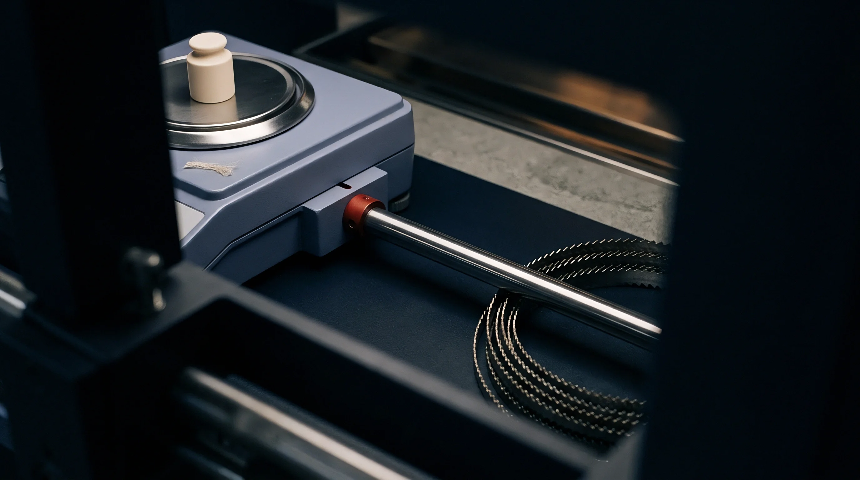
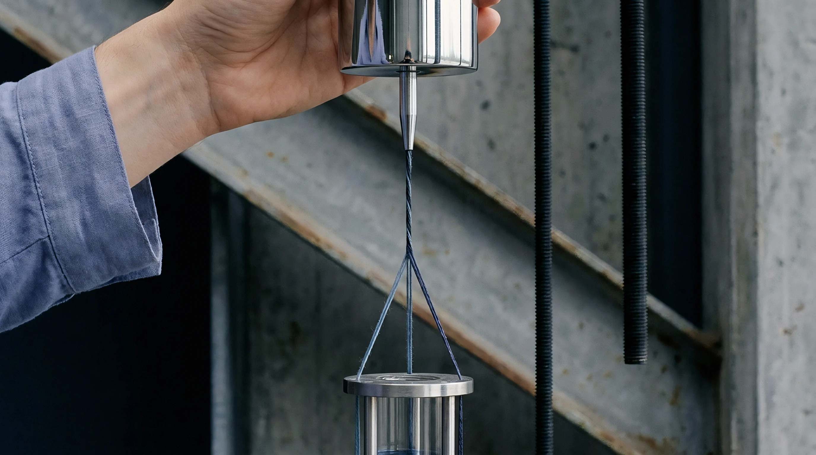
Evaluating complex bending behavior requires automated instrumentation capable of controlled rotational motion. Dedicated pure bending instruments clamp a rectangular fabric strip between two parallel chucks ~ one fixed to a torque transducer, the other mounted to a motorized rotation stage. The drive motor rotates the moveable jaw through preset angular limits while keeping the center of rotation aligned with the specimen’s neutral axis.
Standard procedures run cyclic sweeps between maximum positive and negative curvature, typically within limits of ±2.5 reciprocal centimeters. Drive speeds are strictly controlled at a rate of curvature change around 0.5 reciprocal centimeters per second. Rapid rotation increases viscoelastic resistance artificially, whereas excessively slow rotation exposes load cell readings to signal drift.
Kinematics of Cyclic Pure Bending Testers
Motorized chuck drives rotate opposing grips in equal, synchronized counter-directions to keep the specimen centerline on a true circular arc at all angular positions. Linear translation stages under the drive heads continuously adjust jaw spacing to compensate for chord shortening as curvature increases.
Load cells attached to the stationary jaw record moment values at high sampling frequencies. Signal conditioning filters mechanical motor vibration without smoothing over discrete stick-slip friction events inside the yarn matrix. Continuous digital recording creates dense moment-curvature datasets suitable for precise numerical integration.

Clamping Boundary Conditions and Arc Length
Jaw spacing directly establishes the effective gauge length during deformation. Standard testing rules mandate an active specimen length of 10 mm or 20 mm, paired with a width of 200 mm or 20 mm. Tight clamping tolerances prevent specimen skew, which causes out-of-plane buckling during reverse curvature steps.
Clamping pressure must be calibrated before running test sweeps. Insufficient clamping force allows yarn pull-out, inflating apparent arc length and softening measured rigidity. Excessive force crushes yarns at the grip line, causing localized structural degradation and premature yarn fracture during steep cyclic sweeps.
| Parameter | Cantilever Deflection Tester | KES-FB2 Pure Bending Tester | Optical Cyclic Pure Bending Frame |
|---|---|---|---|
| Active Sample Dimensions | 250 mm x 25 mm | 200 mm x 20 mm | 100 mm x 20 mm |
| Curvature Range (cm⁻¹) | 0.01 to 0.35 (Non-uniform) | -2.5 to +2.5 (Uniform) | -5.0 to +5.0 (Uniform) |
| Curvature Rate (cm⁻¹/s) | Variable (Gravity driven) | 0.50 | 0.01 to 2.00 |
| Moment Measurement Method | Calculated from bend angle | Torque transducer on fixed chuck | Multi-axis load cell with camera verification |
| Shear Contamination Level | High (Mass dependent) | Negligible (< 1%) | Zero (Active compensation) |
| Data compiled under standard atmospheric conditioning per ISO 139 (20°C, 65% RH). Active compensation utilizes real-time linear stage positioning. | |||
Operating a pure bending rig requires systematic verification of grip alignment. Misaligned grips introduce torsional twist along the specimen width, corrupting pure bending moments with out-of-plane shear components.
- Jaw parallelism error causes uneven stress distribution across the width, concentrating strain along one selvedge edge.
- Axis offset drift imposes axial tension during rotation, artificially elevating measured moment readings.
- Transducer zero drift shifts the hysteresis loop off center, distorting positive and negative coercive moment balance.
- Signal noise spikes mask discrete stick-slip friction jumps, hiding structural fiber movement during curvature reversal.
Inconsistent moment readings are sometimes attributed to yarn variance when machine alignment has actually drifted out of tolerance. Regular calibration using standard steel reference strips isolates machine errors from genuine material response.
Metrics
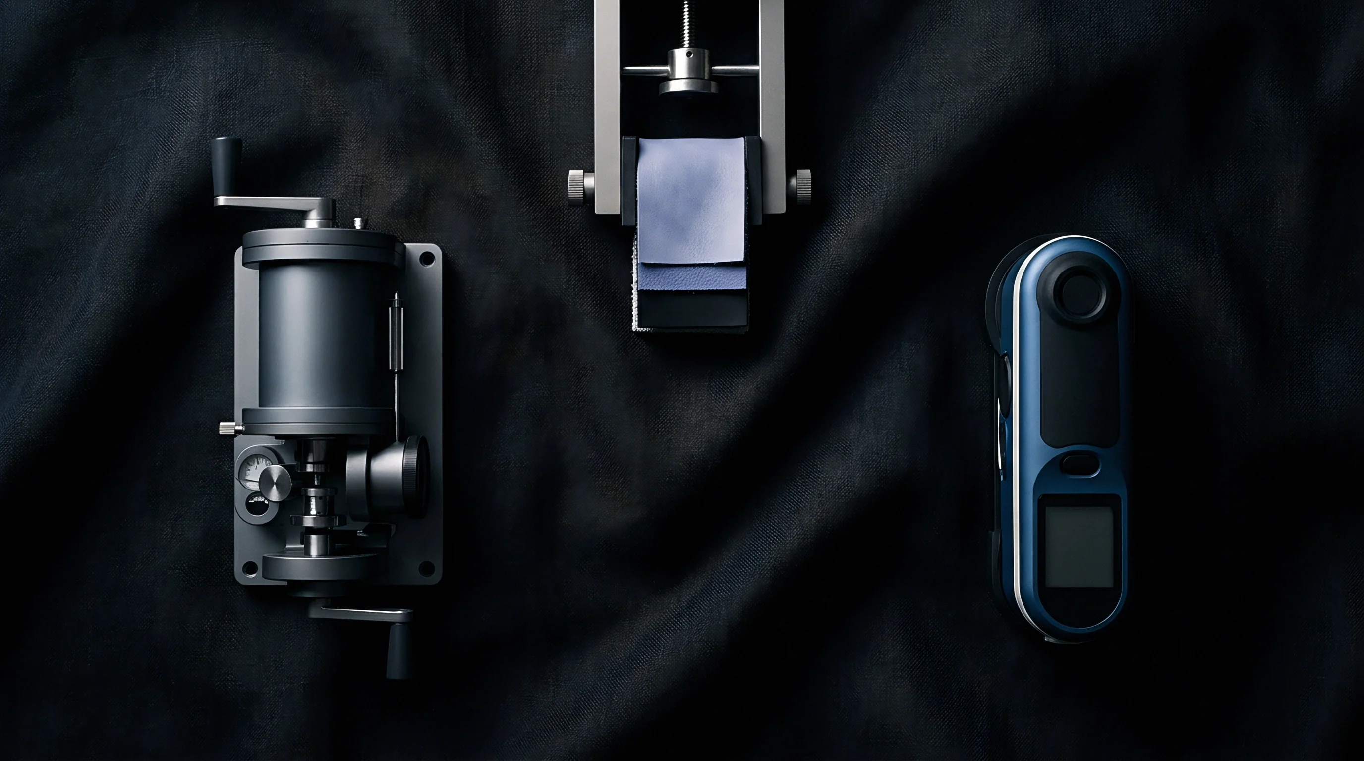
Quantifying mechanical response during flexural cycling generates characteristic moment-curvature loops. Interpreting these curves provides specific numeric indicators describing fabric firmness and internal energy dissipation. The primary parameters extracted from the pure bending hysteresis loop include bending rigidity B, coercive bending moment 2Mo (or 2HB), and hysteresis loop width at specific curvature values 2HB2.
Bending rigidity B represents the slope of the moment-curvature line, measured in cN·cm²/cm or g·cm²/cm, reflecting the force required to bend the fabric by one unit of curvature. The hysteresis metrics 2HB and 2HB2 measure loop width at zero curvature and at a curvature of 1.5 cm⁻¹ respectively, representing energy lost to internal friction during bending.
Quantifying Bending Rigidity and Hysteresis Width
Evaluating the primary slope of the moment-curvature curve yields the flexural stiffness parameter per unit width. Rigidity is evaluated between curvature values of 0.5 cm⁻¹ and 1.5 cm⁻¹ on both forward and reverse loading paths. High values indicate stiff, boardy cloth that resists shaping; low values mark soft, pliable substrates suited for flowing drape designs.
Hysteresis width measures the difference between loading and unloading moments at fixed curvature points. The 2HB value measured at zero curvature reflects residual internal stress locking the deformed structure. Larger loop widths signify greater internal energy loss, preventing the cloth from returning completely to its flat geometry after release.
Comparing two distinct linen cloth constructions illustrates how these metrics behave in practice. Sample A is a 100% linen plain weave (180 g/m², 28 ends/cm, 24 picks/cm, 22 tex yarn), while Sample B is a 100% linen 2/2 twill weave (210 g/m², 36 ends/cm, 30 picks/cm, 22 tex yarn). Pure bending testing on 20 cm wide strips at 0.5 cm⁻¹/s curvature rate yields the raw data analyzed below.
For Sample A (Plain Weave):
- Forward slope gradient between K = 0.5 cm⁻¹ and K = 1.5 cm⁻¹ yields forward stiffness Bf = 0.52 cN·cm²/cm.
- Reverse slope gradient over the same interval yields reverse stiffness Br = 0.48 cN·cm²/cm. Average bending rigidity B = 0.50 cN·cm²/cm.
- Intercept moment difference at K = 0 cm⁻¹ measures 2HB = 0.38 cN·cm/cm.
- Hysteresis loop width at K = 1.5 cm⁻¹ measures 2HB2 = 0.54 cN·cm/cm.
For Sample B (2/2 Twill Weave):
- Forward slope gradient yields Bf = 0.31 cN·cm²/cm.
- Reverse slope gradient yields Br = 0.29 cN·cm²/cm. Average bending rigidity B = 0.30 cN·cm²/cm.
- Intercept moment difference at K = 0 cm⁻¹ measures 2HB = 0.18 cN·cm/cm.
- Hysteresis loop width at K = 1.5 cm⁻¹ measures 2HB2 = 0.26 cN·cm/cm.
The twill weave exhibits 40% lower bending rigidity and 52% lower hysteresis width despite carrying higher areal weight. Float lengths in twill structures reduce yarn crossover points per unit area, lowering inter-yarn frictional constraints during bending.
Can Pure Bending Metrics Predict Garment Formability?
Converting raw laboratory curves into physical performance indices allows cloth buyers to evaluate seam puckering and shell tailoring behavior. Formability parameter F combines bending rigidity B with initial tensile modulus Et across warp and weft threads. High formability values predict smooth tailored contours without structural buckling or seam bubbling during steam pressing.
Low B values paired with excessive hysteresis 2HB create severe garment processing defects. Garment panels shaped under mechanical pressure fail to recover, retaining unwanted wrinkles and press marks. Tailoring shops reject cloth lots that fall outside defined B versus 2HB window boundaries.
| Weave Structure | Ends x Picks (per cm) | Weight (g/m²) | Warp B (cN·cm²/cm) | Weft B (cN·cm²/cm) | Warp 2HB (cN·cm/cm) | Weft 2HB (cN·cm/cm) | Formability Ratio (B/W x 10⁻⁴) |
|---|---|---|---|---|---|---|---|
| Plain Weave | 28 x 24 | 180 | 0.50 | 0.42 | 0.38 | 0.31 | 2.78 |
| 2/1 Twill | 32 x 28 | 195 | 0.38 | 0.31 | 0.25 | 0.20 | 1.95 |
| 2/2 Twill | 36 x 30 | 210 | 0.30 | 0.24 | 0.18 | 0.14 | 1.43 |
| 5-Shaft Satin | 42 x 32 | 230 | 0.22 | 0.17 | 0.11 | 0.08 | 0.96 |
| Average Value | 34.5 x 28.5 | 203.8 | 0.35 | 0.285 | 0.23 | 0.1825 | 1.78 |
Incorporating ISO 139 conditioning rules into greige acceptance contracts prevents batch rejections resulting from humidity-induced hysteresis shift.
Misinterpreting bending metrics leads to expensive manufacturing failures during automated assembly. Choosing a stiff plain weave with high hysteresis for complex curved apparel causes stitch jams, needle cutting, and severe seam puckering along curved hemlines.

Dissipation
Energy loss during cyclic deformation originates from microstructural friction at internal contact interfaces. As a woven sheet bends, individual fibers within spun yarns shift relative to neighboring filaments. Concurrently, warp and weft yarns slide across each other at crossover points.
These micro-movements dissipate input mechanical work into heat through sliding friction.
Frictional energy dissipation creates the characteristic loop width observed in pure bending traces. High yarn-to-yarn contact forces and elevated surface friction coefficients expand the hysteresis area. Conversely, applying lubricating finishes or reducing yarn sett narrows loop width by promoting elastic filament recovery.

Inter-Fiber Friction and Crimp Interchange
Contact points between crossing yarns experience relative displacement as the structure flexes. Bending increases path lengths for yarns on the outer radius while compressing yarns on the inner radius. The resulting tension differentials force crimp interchange, where warp yarns straighten slightly and force weft yarns to increase crimp amplitude.
Resistance to crimp interchange depends heavily on yarn packing density and fiber surface features. Coarse bast fibers like flax possess rough surface scales, generating high frictional resistance during relative movement. This structural characteristic explains why linen textiles exhibit significantly wider hysteresis loops than continuous filament synthetic structures of equivalent weight.
Viscoelasticity and Chemical Finish Interventions
Polymer chain relaxation within individual filaments introduces time-dependent strain recovery behavior. Natural cellulose polymers contain amorphous regions that exhibit viscoelastic dissipation when subjected to bending strains. This molecular friction operates alongside physical inter-fiber surface friction.
Chemical finishing agents modify internal friction dynamics substantially. Applying softeners or silicone emulsions coats fiber surfaces, drastically reducing static and dynamic friction coefficients. Resin cross-linking agents stabilize cell walls, reducing viscoelastic creep and narrowing the hysteresis loop width.
- Silicone softener padding deposits low-surface-energy films on fibers, reducing 2HB values by up to 45 percent.
- Enzyme biopolishing removes surface micro-fibrils, eliminating physical entanglements that restrict inter-yarn sliding during bending.
- Durable press resin treatment locks polymer chains with covalent bonds, decreasing viscoelastic dissipation while increasing overall flexural rigidity B.
- Yarn twist optimization balances filament cohesion; excessively high twist locks fibers, expanding 2HB, while ultra-low twist allows fiber jamming.
Uncertainty remains regarding the precise energy split between inter-fiber surface friction and intra-fiber polymer relaxation during transient high-speed deformation steps. Determining whether friction or viscoelasticity dominates at high deformation frequencies requires further high-speed rheological testing under controlled thermal environments.
Variance
Repeatability in laboratory test data requires strict regulation of ambient atmosphere, specimen handling, and machine calibration. Woven textiles are highly sensitive to environmental moisture and mechanical history. Small shifts in relative humidity alter fiber friction and bending stiffness, while improper specimen cutting introduces artificial edge friction artifacts.
Standardizing test procedures minimizes experimental variance. Adhering to strict specimen preparation standards ensures that measured differences reflect true structural variations rather than laboratory handling inconsistencies.
Standardized Environmental and Conditioning Requirements
Textile structures absorb atmospheric moisture, altering yarn mobility and internal mass properties. Natural cellulose fibers like linen absorb ambient water, which acts as an internal plasticizer within amorphous regions. Increased moisture content reduces fiber modulus while altering surface friction coefficients.
Testing must be conducted in standard atmospheres specified by ISO 139 (20°C ± 2°C and 65% ± 4% relative humidity). Specimens require preconditioning at low humidity before equilibrating in the testing room for a minimum of 24 hours. Testing unconditioned samples directly off production rolls introduces massive data scatter, rendering bending metrics useless for contract qualification.
Cyclic Stabilization and Clamping Pressure Errors
Initial loading passes reorganize disordered yarn structures, shifting hysteretic boundaries across consecutive test sweeps. The first bending cycle exhibits elevated hysteresis width due to overcoming static friction and setting initial fiber alignments. Subsequent cycles settle into a stable, repeatable hysteresis loop.
To establish standardized testing procedures, laboratory technicians follow a strict sequential mounting protocol:
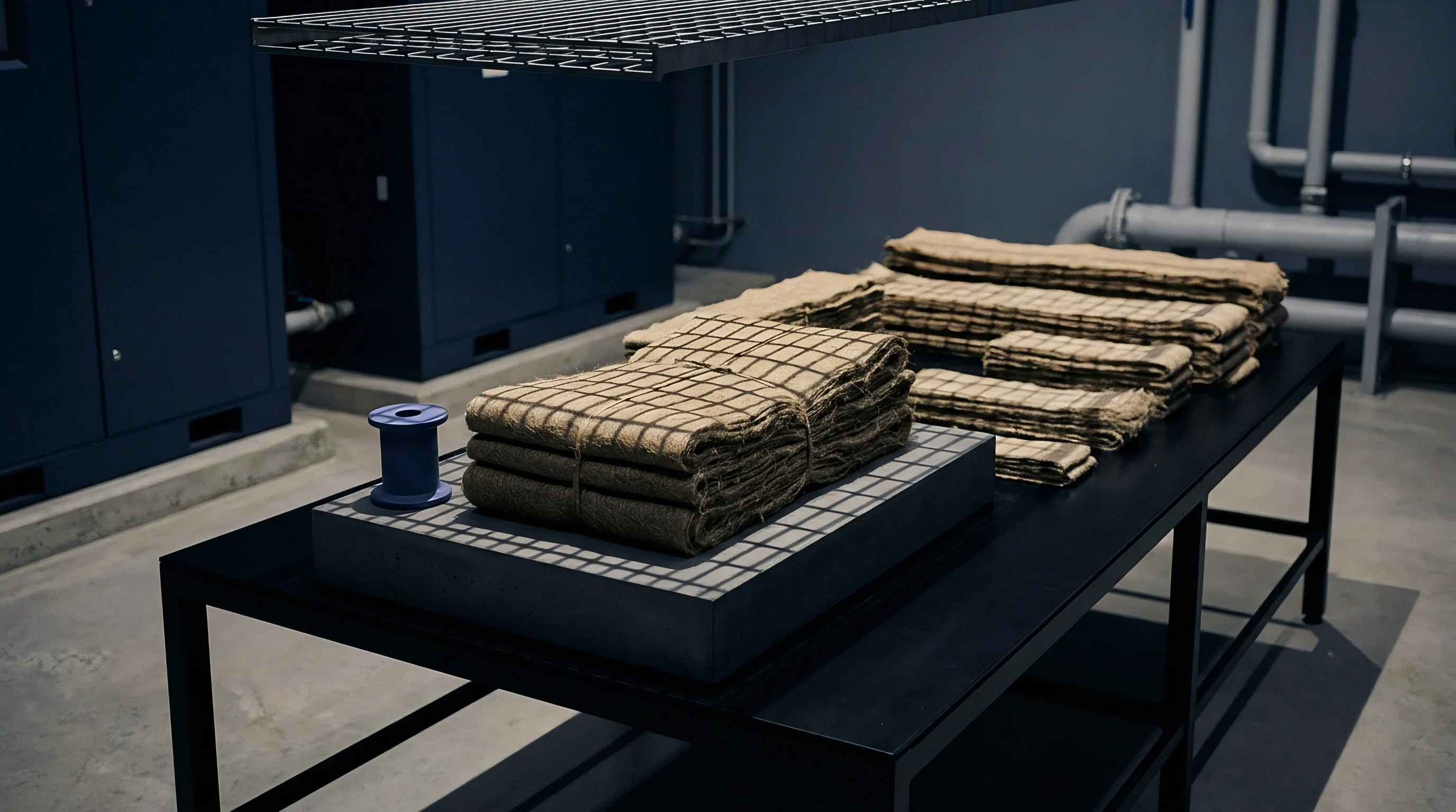
- Cut rectangular specimens measuring 200 mm by 20 mm along exact warp and weft thread lines, discarding damaged selvedge edges.
- Condition prepared strips in a standard atmosphere at 20°C and 65% relative humidity for 24 hours prior to mounting.
- Calibrate load cell zero balances and adjust jaw parallelism alignment using optical alignment gauge blocks.
- Insert specimen ends into clamping jaws, ensuring thread lines run perfectly perpendicular to the clamp edge.
- Torque jaw clamping screws to 0.4 N·m using a calibrated torque wrench to prevent yarn slippage or fiber crushing.
- Execute three preliminary pre-conditioning bending cycles from zero to maximum curvature (+2.5 cm⁻¹) to stabilize internal stress states.
- Record the fourth consecutive moment-curvature cycle dataset for calculation of final B, 2HB, and 2HB2 metrics.
Increasing yarn twist density widens the hysteresis loop area by locking internal fiber contact points against flexural recovery.
Executing pre-conditioning cycles eliminates transient yarn friction variations, yielding reproducible steady-state hysteresis curves.

Specification
Translating physical test parameters into contractual quality limits protects technical buyers against unannounced manufacturing modifications. Pure bending hysteresis metrics provide sensitive indicators of greige yarn changes, finish chemical substitution, or loom setting alterations. Incorporating B and 2HB boundaries into procurement contracts ensures delivered cloth maintains required drape, hand, and processing performance.
Mill adjustments intended to lower landed cost often alter fabric bending performance unintentionally. Substituting lower-grade short-staple fiber, increasing sizing pickup, or reducing finishing wash steps elevates hysteresis width significantly, leading to stiff, poor-draping cloth that buckles during automated cutting.

Translating Hysteresis Data to Production Contracts
Technical procurement documents establish acceptable numeric bands for flexural rigidity and energy loss parameters. Contracts define nominal targets alongside upper and lower tolerance limits for both warp and weft directions. Delivering fabric outside these specification bands triggers financial penalties or lot rejections.
Sourcing engineers specify maximum allowable 2HB limits based on end-use applications. Tailored suitings demand tight 2HB bands to ensure pressing stability, whereas casual apparel accommodates wider hysteresis limits. Clear test protocols attached to purchase orders eliminate disputes regarding test methodology or environmental conditioning.
Loom Capacity and Finishing Line Economics
Modifying weave density or yarn characteristics alters machine throughput speeds and finishing mill operating costs. Reducing pick density lowers bending stiffness B and decreases loom hours required per hundred meters, reducing greige weaving costs. However, lower pick counts reduce cloth cover factor and mass, requiring weight compensation through heavier yarn counts.
Chemical finish applications offer a cost-effective route to lower hysteresis without altering loom construction settings. Applying silicone softeners during tentering reduces 2HB quickly, but increases chemical pad costs per meter. Sourcing desks evaluate these trade-offs to balance landed metre costs against physical bending requirements.
| Process Modification | Mechanism of Action | Bending Rigidity B Delta (%) | Hysteresis 2HB Delta (%) | Finishing Cost Delta (EUR/m) | Loom Efficiency Impact |
|---|---|---|---|---|---|
| Yarn Twist Reduction (-10%) | Increases fiber mobility within yarn core | -12% | -18% | 0.00 | Reduces warp end breaks by 3% |
| Enzyme Biopolishing Pass | Removes surface fibrils and smooths fiber surface | -8% | -32% | +0.22 | Neutral (Post-weave wet process) |
| Silicone Micro-Emulsion Pad | Lowers inter-fiber surface friction coefficient | -15% | -42% | +0.18 | Neutral (Post-weave wet process) |
| Weft Sett Reduction (-5%) | Decreases crossover contact points per cm² | -18% | -22% | -0.05 | Increases weaving speed by 5% |
Quality assurance clauses in commercial delivery agreements mandate that delivered cloth lots must pass pure bending hysteresis verification per ISO standard testing protocols, where any lot exhibiting a mean 2HB hysteresis width exceeding specified limits by more than 10 percent shall be rejected at the supplier cost.