Calculating Warp End Density Limits in High Density Woven Fabrics
Calculating maximum warp end density requires adjusting Peirce geometric jamming models for yarn compaction, reed clearance, and shed beat-up force limits.

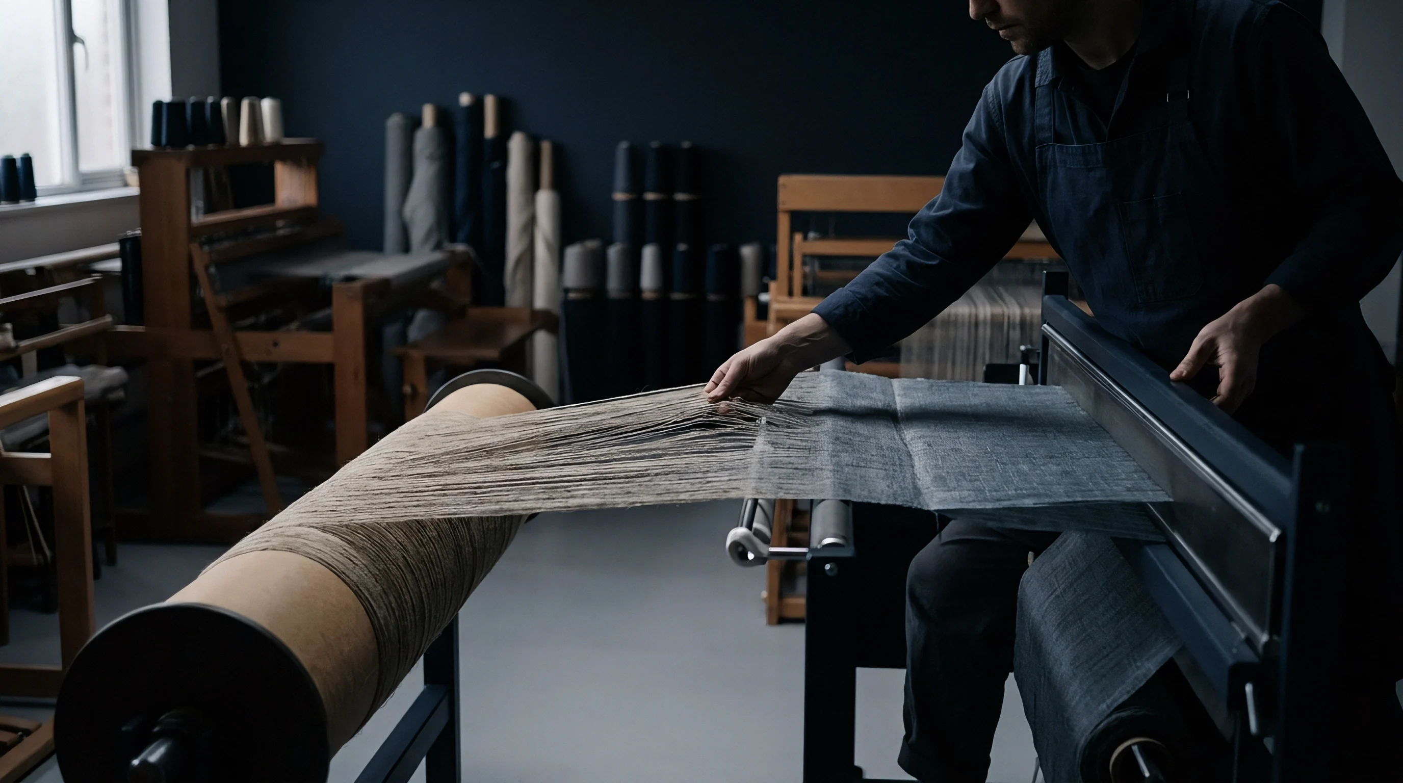
Jamming
Thread packing in woven structures reaches an absolute geometric threshold when adjacent warp threads touch along their longitudinal axis under full weave tension. Determining this limit prevents warp yarn shear, excessive beat-up resistance, and catastrophic shed obstruction during high-speed insertion. Yarn cross-sections do not remain perfect circles inside dense woven structures.
Internal lateral pressure during beat-up flattens circular yarns into elliptical geometries, altering the theoretical packing limit calculated from circular yarn diameters.
Calculating maximum warp thread density requires establishing the yarn diameter from thread count and fiber bulk density. Cotton system count translates to theoretical diameter through standard packing coefficients. A combed cotton yarn at 40s Ne yields a nominal uncompressed diameter of 0.133 millimeters based on a fiber density of 1.54 grams per cubic centimeter and a packing fraction of 0.60.
Placing these ends edge-to-edge without pick insertion suggests a limit of 75 ends per centimeter. The interlace geometry of plain weave reduces this theoretical ceiling. Inserting a weft thread forces the warp ends to bend above and below the cloth neutral plane, consuming axial width and reducing the maximum allowable warp end density by a factor dictated by thread crimp.
ISO 7211 establishes the standard test protocol for determining thread density and crimp percentages in woven fabric samples.
Ashenhurst derived an early empirical coefficient assuming circular yarns and fixed crimp distribution, postulating that maximum warp density in plain weave equals 0.707 multiplied by the maximum open thread count. Modern high-density technical textiles and down-proof cotton constructions exceed Ashenhurst boundaries by utilizing high tension and low-friction sizing compositions. Peirce refined this model by incorporating yarn flexibility and elliptical distortion ratios.
When warp threads flatten under loom tension, the major horizontal axis increases while the vertical axis contracts, permitting higher end counts per unit width at the cost of elevated warp-to-warp friction in the reed dentes.
Exceeding maximum geometric packing limits alters fabric mechanical properties and destabilizes the weaving process. Over-packed warp yarns jam against adjacent ends during shedding. The harness frames strain to split the upper and lower shed lines, generating high warp tension spikes.
These tension surges cause end breaks, friction marks, and excessive reed wear. Fabrics constructed beyond their physical density limit exhibit severe width contraction upon release from loom tension, leading to unstable cloth margins and permanent warp-way streak defects.

Reed
Beat-up force spikes non-linearly when warp end density approaches the structural jamming point. The reed wire must physically separate adjacent warp ends while pushing the newly inserted pick into the fell of the cloth. High-density warp configurations reduce the open space between reed wires, forcing multiple ends into a single dent or demanding ultra-fine reed wire profiles that deflect under shed pressure.
Reed wire deflection creates uneven dent spacing, producing persistent longitudinal lines known as reed marks across the finished fabric width.
Selecting the denting plan requires balancing wire thickness against the space available for warp passage. A 100-dent-per-inch reed constructed with standard 0.12-millimeter wire leaves an open gap of only 0.134 millimeters per dent. Passing two ends of 50s Ne cotton yarn through this gap results in continuous lateral abrasion between yarn body and stainless steel wire during harness movement.
Choosing a single-end denting arrangement mitigates yarn-to-yarn friction inside the dent, but doubles the total number of reed wires required, increasing beat-up resistance across the full reed width.
| Yarn Count (Ne) | Ends Per Dent | Reed Count (Dents/cm) | Wire Thickness (mm) | Effective Dent Gap (mm) | Clearance Ratio (%) |
|---|---|---|---|---|---|
| 30/1 | 2 | 24.0 | 0.180 | 0.236 | 26.4 |
| 40/1 | 2 | 32.0 | 0.150 | 0.162 | 21.8 |
| 60/1 | 3 | 28.0 | 0.130 | 0.227 | 18.5 |
| 80/1 | 3 | 36.0 | 0.100 | 0.177 | 16.2 |
| 100/2 | 2 | 40.0 | 0.090 | 0.160 | 19.1 |
Shedding geometry defines the vertical clearance available as threads cross during pick insertion. High density warps demand smaller shed openings to minimize total yarn elongation and prevent warp breaks. A reduced shed opening restricts weft insertion timing windows on air-jet and rapier machines.
If the shed fails to clear cleanly before insertion, the main nozzle blast or rapier head strips loose fibers from the warp body, creating cling faults and micro-loops along the selvage.
Can a loom maintain 85 percent shedding efficiency when warp end density exceeds 82 percent of the theoretical Peirce limit?
Mills often compensate for high beat-up resistance by applying asymmetric shed timing or off-setting the harness drop. Advancing the shedding motion causes warp threads to cross before the reed completes its forward stroke, locking the pick into position under active shed tension. This technique prevents pick rebound in dense weaves, but amplifies warp stress by up to 35 percent at the exact instant of maximum beat-up force.
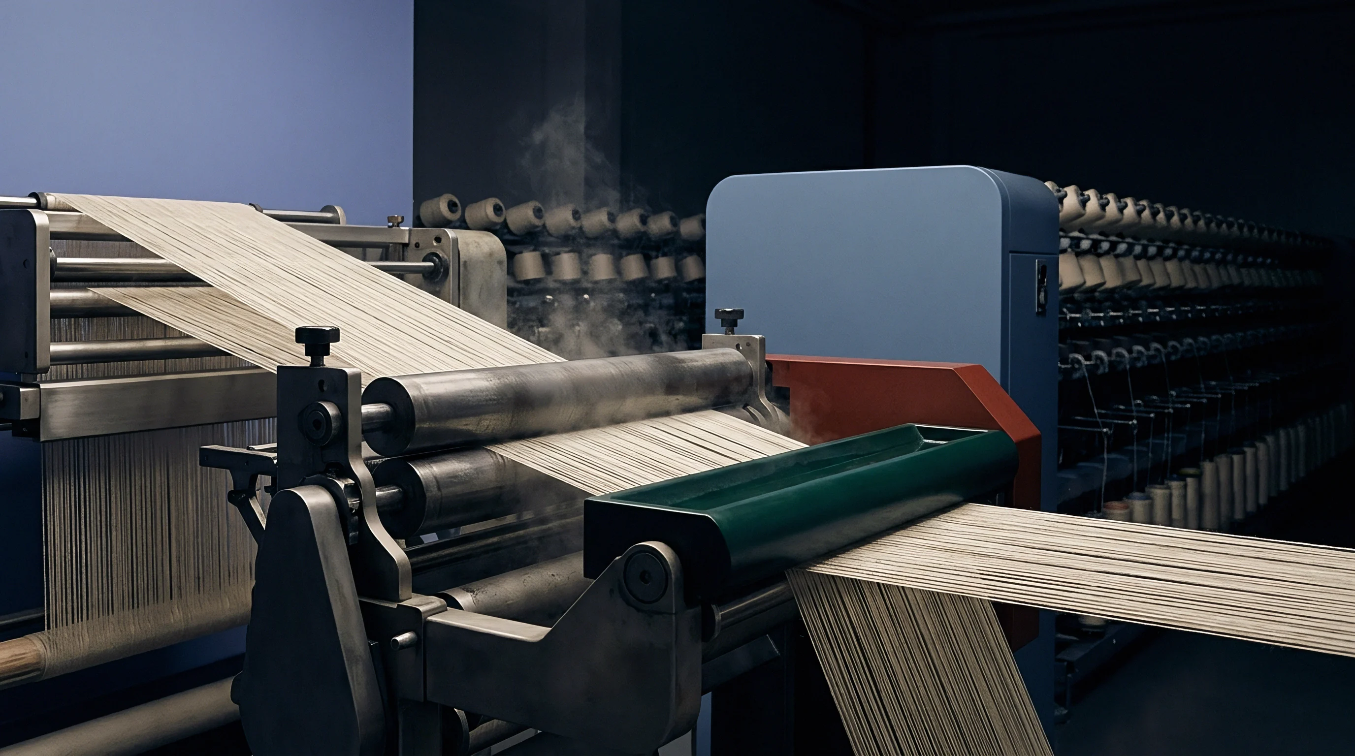
Abrasion
Friction between adjacent warp threads during harness alternation causes surface fuzzing, filamentation, and thread rupture long before the yarn reaches the cloth fell. High warp end densities reduce the physical clearance between ends to dimensions smaller than the protruding surface fibers of ring-spun yarns. As drop wires and heddles cycle thousands of times per hour, loose surface fibers interlace between neighboring threads, creating fiber bridges that impede clean shed separation.
Sizing formulations engineered for dense warps prioritize film toughness and low surface kinetic friction over simple tensile addition. Polyvinyl alcohol and synthetic polymer binders coat the yarn body, encapsulating loose fibers and elevating yarn-to-yarn abrasion resistance. The size add-on percentage for high-density constructions ranges between 12 percent and 16 percent by dry weight, compared to 8 percent for standard apparel fabrics.
Excessive size application makes the warp brittle, increasing end breakage rates under high beat-up tension.
Applying low-friction lubricants during sizing reduces warp-to-warp mechanical drag inside the drop wire box.
Monitoring warp thread micro-abrasion requires evaluation on constant-tension fatigue testers before committing full warp beams to the shed. Standard test methods measure cycles to failure under cyclic tension and reciprocating friction bars. Sized yarns intended for dense plain weaves must withstand a minimum of 1,500 friction cycles on a yarn abrasion tester without exhibiting coat rupture or fiber lint buildup.
- Film Strength Index measures binder resistance to mechanical shearing caused by heddle eye friction during high-frequency shedding cycles.
- Hairiness Suppression Ratio quantifies the percentage reduction of surface fibers exceeding 3 millimeters in length following sizing application.
- Moisture regain percentage dictates binder elasticity, requiring strict control between 6.5 percent and 7.5 percent relative humidity inside the loom shed.
- Size Penetration Depth defines binder distribution, where target values equal 20 percent to 30 percent of the total yarn cross-sectional area.
Engineers often hear mill operators attribute severe warp shedding faults to poor yarn quality rather than structural over-density. The shed floor frequently claims that lower yarn tenacity caused the excessive stop rate, masking the reality that the specified end count forced adjacent threads into continuous mechanical interference inside the harness eyes.

Equations
Calculating the upper warp end density limit requires systematic mathematical modeling incorporating fiber density, yarn number system, weave structure factor, and compaction allowances. The foundational relationship relies on the direct calculation of theoretical yarn diameter, modified by empirical geometry coefficients.
Calculate yarn diameter using direct indirect count conversions:
d = 1 / (K sqrt(Ne))
For cotton yarn systems, d represents diameter in inches, Ne represents English Cotton Count, and K represents the fiber packing constant, standardized at 28 for ring-spun cotton yarns. Converting to metric units yields the working equation:
d_mm = 0.907 / sqrt(Ne)
The weave structure factor accounts for thread interlace frequency per repeat unit. Plain weave contains two interlaces per two threads, providing maximum structural displacement. Twill 2/2 contains two interlaces per four threads, reducing warp crimp displacement and allowing higher thread packing densities.
The fractional cover factor calculation models these geometry variations:
Cover Factor = End Density (ends/cm) d_mm / 10
Maximum theoretical warp density for a fully compacted, non-deformed plain weave cloth aligns with Peirce’s geometric jam formula:
Ends_max (ends/cm) = 10 / (d_mm (1 + (c_w / 100)))
In this equation, c_w represents warp crimp percentage at weaving tension, typically ranging between 4 percent and 9 percent for high-density specifications.
| Construction Metric | Plain Weave (1/1) | Twill (2/1) | Twill (2/2) | Satin (5-shaft) |
|---|---|---|---|---|
| Weave Interlace Factor | 1.00 | 0.67 | 0.50 | 0.40 |
| Ashenhurst Density Factor | 0.707 | 0.750 | 0.800 | 0.890 |
| Max Ends/cm (40s Ne Yarn) | 53.0 | 56.2 | 60.0 | 66.7 |
| Max Fractional Cover Factor | 0.76 | 0.81 | 0.86 | 0.96 |
| Calculated Beat-up Load (N/m) | 1450 | 1120 | 890 | 620 |
Consider a practical engineering evaluation for specifying a down-proof cotton fabric. Assume a required yarn count of 60s Ne combed cotton. The calculated uncompressed diameter equals 0.117 millimeters.
Utilizing the standard Peirce jamming calculation for plain weave with an assumed warp crimp of 6 percent yields:
Ends_max = 10 / (0.117 (1 + 0.06)) = 80.6 ends/cm
Applying an operational safety margin of 8 percent prevents excessive loom stops, setting the maximum practical specification limit at 74.1 ends per centimeter. If the product requirement demands 82 ends per centimeter at 60s Ne in plain weave, the warp will enter the jam zone during weaving. Achieving this density requires switching from ring-spun to compact yarn, elevating the yarn packing coefficient K from 28 to 31, which compresses the effective diameter to 0.105 millimeters and shifts the jamming boundary to 89.8 ends per centimeter.
Maximum warp density scales directly with yarn compactness and weave float length.

Penalties
Pushing warp end counts into structural jam zones carries quantifiable economic consequences across loom shed production, greige fabric inspection, and wet processing yields. Running looms at high warp densities forces reductions in insertion speed to maintain acceptable warp break rates. An air-jet loom rated at 1,000 picks per minute on standard utility fabrics often drops to 650 picks per minute when weaving high-cover constructions to avoid excessive thread abrasion in the reed.
Speed reductions directly alter machine-hour allocations and landed metre costs. Operating a loom shed at reduced speed increases fixed overhead absorption per produced metre. Warp stops skyrocket when density exceeds 92 percent of the Peirce limit, moving from an acceptable 1.2 stops per 100,000 picks to over 8.5 stops per 100,000 picks.
Each stop creates a potential defect, increasing starting marks, thick places, and tail ends that degrade greige fabric quality grades under four-point inspection systems.
- Stop rate escalations reduce total weaver section allocations from 24 machines down to 8 machines per operator.
- Starting mark frequency increases, causing up to 6 percent total fabric length downgrades at the inspection frame.
- Primary nozzle air consumption rises by 22 percent on air-jet looms due to extended blown-dwell times needed to clear tight sheds.
- Off-loom width contraction increases by 4 percent, requiring wider reed drawing and higher greige yarn usage per finished metre.
| Density % of Peirce Limit | Loom Speed (RPM) | Shed Efficiency (%) | Warp Stops / 10^5 Picks | Relative Production Cost / Metre |
|---|---|---|---|---|
| 70% – Standard | 950 | 91.5 | 0.8 | 1.00 |
| 80% – High Density | 850 | 88.0 | 1.5 | 1.14 |
| 90% – Extreme Density | 700 | 81.2 | 4.2 | 1.42 |
| 95% – Structural Jam Zone | 580 | 72.0 | 9.6 | 1.88 |
Off-loom relaxation introduces substantial width loss when warp densities approach physical limits. Internal lateral pressures force the fabric to draw in immediately upon releasing warp tension at the take-up roller. A cloth woven at 170 centimeters reed width under high tension can collapse to 156 centimeters greige width, introducing massive warp crimp amplification that causes severe dimensional instability during wet processing and scouring.
ASTM D5430 provides the standardized point scoring matrix for evaluating visual fabric defects during greige inspection.
Standard purchasing contracts hedge against structural over-density by specifying strict operational efficiency boundaries. Standard supply agreements stipulate that if a requested warp density forces machine efficiency below 80 percent or generates defect scores exceeding 28 points per 100 square meters under four-point inspection, the buyer absorbs the loom-hour speed surcharge or alters the construction to a higher float weave structure.